
Intermolecular Forces
In the following description, the term particle will be used as a collective term to refer to an atom, molecule, or ion. Note that we will use the popular phrase “intermolecular attraction” to refer to attractive forces between the particles of a substance, regardless of whether these particles are molecules, atoms, or ions.
Consider these two aspects of the molecular-level environments in solid, liquid, and gaseous matter:
- Particles in a solid are tightly packed together and often arranged in a regular pattern; in a liquid, they are close together with no regular arrangement; in a gas, they are far apart with no regular arrangement.
- Particles in a solid vibrate about fixed positions and do not generally move in relation to one another; in a liquid, they move past each other but remain in essentially constant contact; in a gas, they move independently of one another except when they collide.
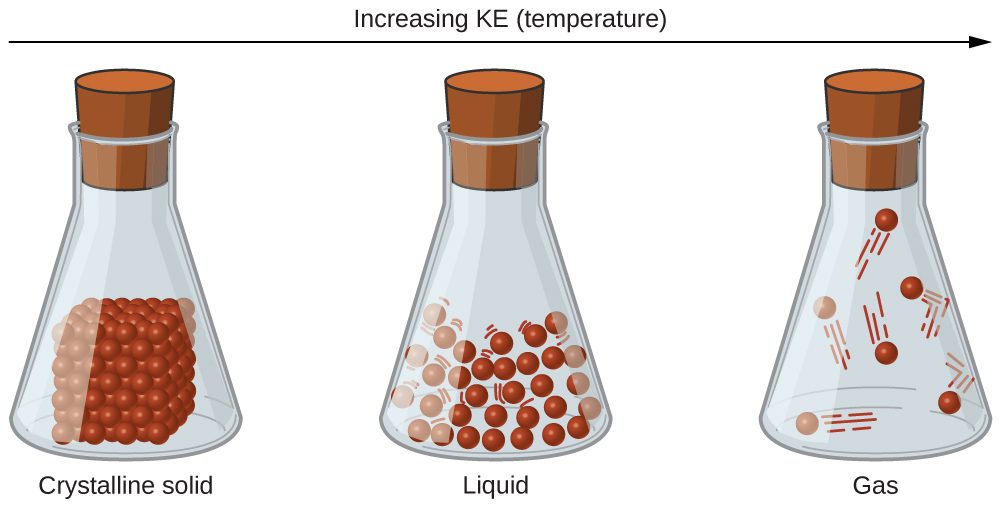
The differences in the properties of a solid, liquid, or gas reflect the strengths of the attractive forces between the atoms, molecules, or ions that make up each phase. The phase in which a substance exists depends on the relative extents of its intermolecular forces (IMFs) and the kinetic energies (KE) of its molecules. IMFs are the various forces of attraction that may exist between the atoms and molecules of a substance due to electrostatic phenomena. Here, we will use the phase of a substance as an approximation of its IMFs, with solids having the strongest IMFs and gases having the weakest. These forces serve to hold particles close together, whereas the particles’ KE provides the energy required to overcome the attractive forces and thus increase the distance between particles. Figure 1 illustrates how changes in physical state may be induced by changing the temperature, hence the average KE, of a given substance.
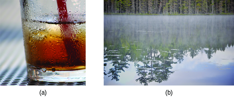
As an illustration of a process depicted in this figure, consider a sample of water vapor. When gaseous water is cooled sufficiently, by coming into contact with a cold surface for example, the attractions between H2O molecules will be capable of holding the molecules together when they come into contact with each other; the gas condenses, forming liquid H2O. For example, liquid water forms on the outside of a cold glass as the water vapor in the air is cooled by the cold glass, as seen in Figure 2.
Finally, if the temperature of a liquid becomes sufficiently low, or the pressure on the liquid becomes sufficiently high, the molecules of the liquid no longer have enough KE to overcome the IMF between them, and a solid forms.
Intramolecular Forces vs. Intermolecular Forces
 Intermolecular attractive forces are present in all substances as evidenced by the fact that everything will eventually solidify under appropriate conditions. They may be very weak, as is the case with the noble gases, but eventually even these atomic substances will liquify and then freeze if the temperature drops low enough. This is a result of the intermolecular forces as opposed to intramolecular forces. Intramolecular forces are those within a molecule that keep the atoms bonded together as an integral molecular unit. Intermolecular forces are the attractions between molecules or non bonded atoms, which determine many of the physical properties of a substance.
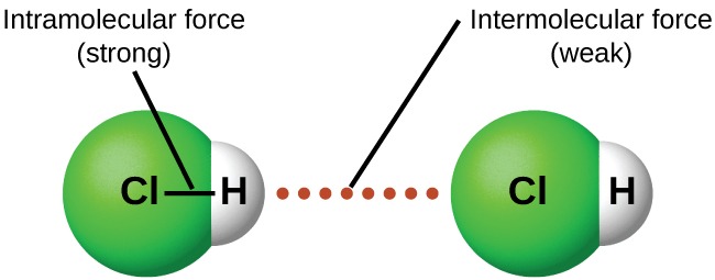
The strengths of IMFs vary widely, though usually the IMFs between small molecules are weak compared to the intramolecular forces that bond atoms together within a molecule. For example, to overcome the IMFs in one mole of liquid HCl(ℓ) and convert it into gaseous HCl(g) (a physical change) requires only about 17 kJ. However, to break the covalent bonds between the hydrogen and chlorine atoms (a chemical change) in one mole of HCl requires about 25 times more energy—430 kJ. Attractive forces between neutral atoms and molecules are known collectively as van der Waals forces, although they are usually referred to more informally as intermolecular attraction. We will consider the various types of IMFs below.
Dispersion Forces
One of the van der Waals forces is present in all condensed phases, regardless of the nature of the atoms or molecules composing the substance. This attractive force is called the London dispersion force in honor of German-born American physicist Fritz London who, in 1928, first explained it.
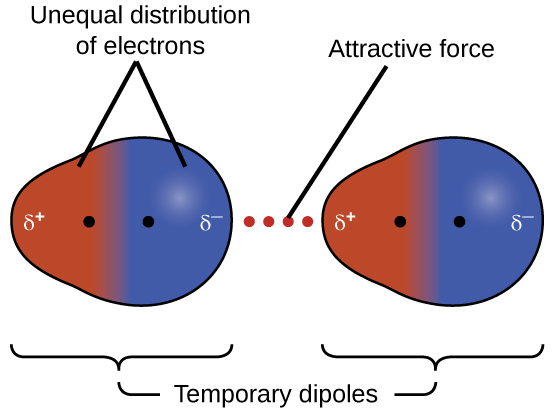
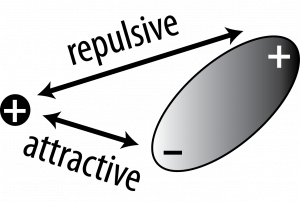
This force is often referred to as simply the dispersion force or London force. Because the electrons of an atom or molecule are in constant motion (or, alternatively, the electron’s location is subject to quantum-mechanical variability), at any moment in time, an atom or molecule can develop a temporary, instantaneous dipole if its electrons are distributed asymmetrically, as shown in Figure 3.
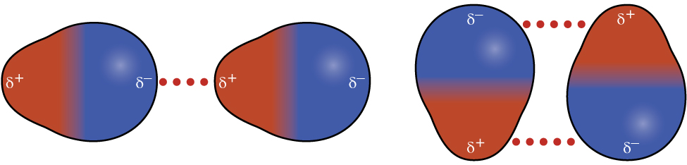
The presence of this transient dipole can, in turn, distort the electrons of a neighboring atom or molecule in the sample, producing an induced dipole in the other molecule. Another name for this type of force is instantaneous dipole-induced dipole, though this term is less commonly used in our course. These two rapidly fluctuating, temporary dipoles thus result in a relatively weak electrostatic attraction between the species—a so-called dispersion force like that illustrated in Figure 4.
Dispersion forces that develop between atoms in different molecules can attract the two molecules to each other. The forces are relatively weak, however, and become significant only when the molecules are very close. Larger atoms and molecules, with more electrons, exhibit stronger dispersion forces than do smaller atoms and molecules. F2 (18 electrons) and Cl2 (34 electrons) are gases at room temperature (reflecting weaker attractive forces); Br2 (70 electrons) is a liquid, and I2 (106 electrons) is a solid (reflecting stronger attractive forces).
In a larger atom, the valence electrons are, on average, farther from the nuclei than in a smaller atom. Thus, the electrons are less tightly held and can more easily form the temporary dipoles that produce this attraction. The measure of how easy or difficult it is for another electrostatic charge (for example, a nearby ion or polar molecule) to distort a molecule’s charge distribution (its electron cloud) is known as polarizability. A molecule that has a charge cloud that is easily distorted is said to be very polarizable and a bulk sample will have relatively strong dispersion forces; one with a charge cloud that is difficult to distort is not very polarizable and a bulk sample will have relatively weak dispersion forces.
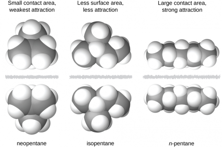 The shapes of molecules also affect the magnitudes of the dispersion forces between them. For example, consider the isomers n-pentane, isopentane, and neopentane. Even though these compounds are composed of molecules with the same chemical formula, C5H12, the dispersion forces in the liquid phase are different, being greatest for n-pentane and least for neopentane. The elongated shape of n-pentane provides a greater surface area available for contact between molecules, resulting in correspondingly stronger dispersion forces. The more compact shape of isopentane offers a smaller surface area available for intermolecular contact and, therefore, weaker dispersion forces. Neopentane molecules are the most compact of the three, offering the least available surface area for intermolecular contact and, hence, the weakest dispersion forces. This behavior is analogous to the connections that may be formed between strips of VELCRO brand fasteners: the greater the area of the strip’s contact, the stronger the connection.
Chemistry in Real Life: Geckos and Intermolecular Forces
Geckos have an amazing ability to adhere to most surfaces. They can quickly run up smooth walls and across ceilings that have no toe-holds, and they do this without having suction cups or a sticky substance on their toes. And while a gecko can lift its feet easily as it walks along a surface, if you attempt to pick it up, it sticks to the surface. How are geckos (as well as spiders and some other insects) able to do this? Although this phenomenon has been investigated for hundreds of years, scientists only recently uncovered the details of the process that allows geckos’ feet to behave this way.
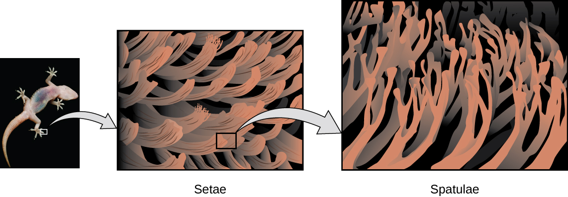
Geckos’ toes are covered with hundreds of thousands of tiny hairs known as setae, with each seta, in turn, branching into hundreds of tiny, flat, triangular tips called spatulae. The huge numbers of spatulae on its setae provide a gecko with a large total surface area for sticking to a surface.
In 2000, Kellar Autumn, who leads a multi-institutional gecko research team, found that geckos adhered equally well to both polar silicon dioxide and nonpolar gallium arsenide. This proved that geckos stick to surfaces because of dispersion forces—weak intermolecular attractions arising from temporary, synchronized charge distributions between adjacent molecules. Although dispersion forces are very weak, the total attraction over millions of spatulae is large enough to support many times the gecko’s weight.
In 2014, two scientists developed a model to explain how geckos can rapidly transition from “sticky” to “non-sticky.” Alex Greaney and Congcong Hu at Oregon State University described how geckos can achieve this by changing the angle between their spatulae and the surface. Geckos’ feet, which are normally nonsticky, become sticky when a small shear force is applied. By curling and uncurling their toes, geckos can alternate between sticking and unsticking from a surface, and thus easily move across it. Further investigations may eventually lead to the development of better adhesives and other applications.
Dipole-Dipole Attractions
Polar molecules have a partial positive charge on one side and a partial negative charge on the other side of the molecule—a separation of charge called a dipole. Consider a polar molecule such as hydrogen chloride, HCl. In the HCl molecule, the more electronegative Cl atom bears the partial negative charge, whereas the less electronegative H atom bears the partial positive charge. An attractive force between HCl molecules results from the attraction between the positive end of one HCl molecule and the negative end of another. This attractive force is called a dipole-dipole attraction—the electrostatic force between the partially positive end of one polar molecule and the partially negative end of another, as illustrated in Figure 5.
The effect of a dipole-dipole attraction is apparent when we compare the properties of HCl to nonpolar F2. Both HCl and F2 are diatomic molecules with approximately the same number of electrons and therefore bulk samples of these substances would have comparable London forces. However, HCl(ℓ) has a much higher boiling point (188 K) compared to F2(ℓ) (85 K), an indication that HCl(ℓ) has stronger IMFs as a result of dipole-dipole attractions in addition to the London forces.
Hydrogen Bonding
Nitrosyl fluoride (ONF) is a gas at room temperature. Water (H2O) is a liquid, even though it has fewer electrons. We clearly cannot attribute this difference between the two compounds to dispersion forces. Both molecules have about the same shape and ONF is the larger molecule. It is, therefore, expected to experience more significant dispersion forces. Additionally, we cannot attribute this difference to differences in the dipole moments of the molecules. Both molecules are polar and exhibit comparable dipole moments. The difference is due to a particularly strong interaction that may occur when a molecule contains a hydrogen atom bonded to a fluorine, oxygen, or nitrogen atom (three of the most electronegative elements). The very large difference in electronegativity between the H atom (2.2) and the atom to which it is bonded (4.0 for an F atom, 3.5 for an O atom, or 3.1 for a N atom), combined with the very small size of a H atom and the relatively small sizes of F, O, or N atoms, leads to highly concentrated partial charges with these atoms. Molecules with F-H, O-H, or N-H groups are very strongly attracted to similar groups in nearby molecules, and a particularly strong intermolecular interaction, called hydrogen bonding, is formed. This hydrogen bond forms from the interaction between the lone pair of electrons on an N, O, or F atom (the electron donor) and the empty antibonding orbital of a highly polarized F-H, O-H, or N-H sigma bond (the electron acceptor). Examples of hydrogen bonds include HF⋯HF, H2O⋯HOH, and H3N⋯HNH2, in which the hydrogen bonds are denoted by dots.
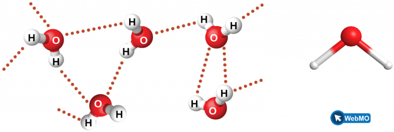
Figure 6 illustrates hydrogen bonding between water molecules. Notice that the hydrogen bond forms between a hydrogen that is attached to an oxygen atom on one molecule and an oxygen atom on an adjacent molecule. This example highlights the two requirements for forming a hydrogen bond: (1) One molecule must have an H atom bonded to an N, O, or F atom; and (2) another molecule must have an N, O, or F atom with a lone pair of electrons.
Despite use of the word “bond,” keep in mind that hydrogen bonds are much weaker than covalent bonds, only about 5 to 10% as strong, but are generally stronger than dipole-dipole attractions and dispersion forces. For example, hydrogen bonds have a pronounced effect on the properties of condensed phases (liquids and solids).
So far we have emphasized that IMFs are between separate molecules, but this is not always the case. In very large molecules such as proteins or DNA, these IMFs can occur within the same molecule and help stabilize their three-dimensional structure, which is essential for their mode of operation. The hydrogen bonding in DNA is described below.
Chemistry in Real Life: Hydrogen Bonding and DNA
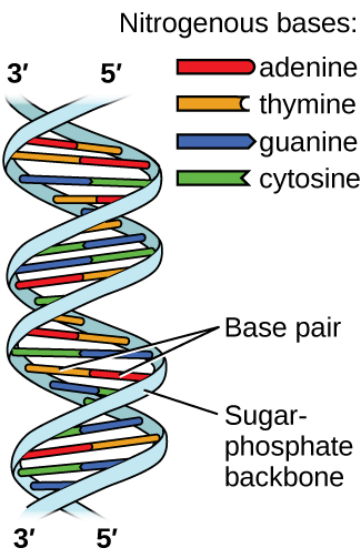 Deoxyribonucleic acid (DNA) is found in every living organism and contains the genetic information that determines the organism’s characteristics, provides the blueprint for making the proteins necessary for life, and serves as a template to pass this information on to the organism’s offspring. A DNA molecule consists of two (anti-)parallel chains of repeating nucleotides, which form its well-known double helical structure.
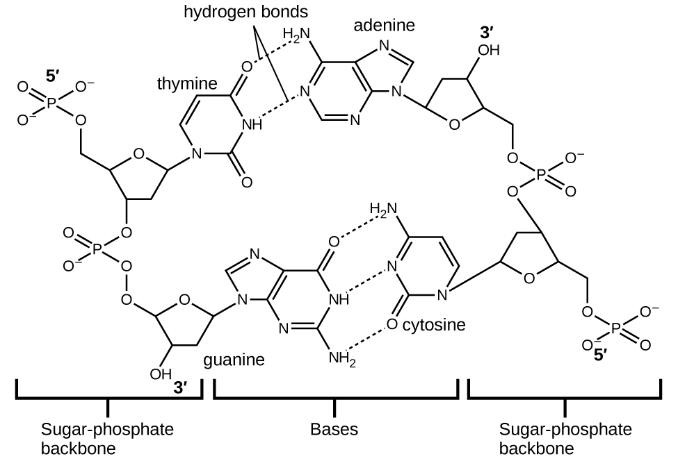
Each nucleotide contains a (deoxyribose) sugar bound to a phosphate group on one side, and one of four nitrogenous bases on the other. Two of the bases, cytosine (C) and thymine (T), are single-ringed structures known as pyrimidines. The other two, adenine (A) and guanine (G), are double-ringed structures called purines. These bases form complementary base pairs consisting of one purine and one pyrimidine, with adenine pairing with thymine, and cytosine with guanine. Each base pair is held together by hydrogen bonding. A and T share two hydrogen bonds, C and G share three, and both pairings have a similar shape and structure (Figure 7).
The cumulative effect of millions of hydrogen bonds effectively holds the two strands of DNA together. Importantly, the two strands of DNA can relatively easily “unzip” down the middle since hydrogen bonds are relatively weak compared to the covalent bonds that hold the atoms of the individual DNA molecules together. This allows both strands to function as a template for replication.
The Special Role of Hydrogen Bonding in Water
Almost all substances become less dense when they are heated (as they expand slightly) and more dense when they are cooled. Above 4 °C water is no exception, but below 4 °C as it is cooled further, liquid water actually expands a little and the density decreases slightly. Upon actually freezing at 0 °C, there is a much larger expansion as the volume increases by about 9% with a corresponding drop in density as the liquid water becomes solid ice. In H2O(s) each water molecule makes four hydrogen bonds with its neighbors resulting in a three dimensional array with an open hexagonal structure, more open and therefore with a greater volume compared to the same amount of H2O(ℓ). Between 4 °C and 0 °C, the water molecules are beginning to orient themselves and so the liquid expands as it gets close to actually freezing. You have likely found that if you place a full water bottle in the freezer, the plastic bottle will begin to bulge as the solid water occupies more space than the liquid water.
The expansion of ice as it freezes means that ice floats on top of water. This characteristic is vital to the survival of organisms in cold climates like Wisconsin. During the winter, as Lake Mendota begins to freeze, the surface of the water freezes first; people often enjoy skating or skiing across frozen lakes when the ice is thick enough. The ecosystem is able to survive in the unfrozen water beneath the surface because the ice insulates it, providing an adequate living temperature. If water froze and sank to the bottom, lakes would freeze from the bottom up and become completely frozen during winter. The summer is not long enough in Wisconsin to melt all of the water in the frozen lakes, and fish and other organisms would be unable to survive.
Some Other IMFs
Dipole-Induced Dipole Interactions
Above, we learned that at any moment, an atom or nonpolar molecule can experience an instantaneous dipole if its electrons are asymmetrically distributed, and that this instantaneous dipole can induce a dipole in a neighboring atom or molecule.
 If a molecule with an established dipole were in proximity to a nonpolar molecule, however, it follows that the established dipole will induce a dipole in the nonpolar molecule. This type of interaction between a polar molecule and a nonpolar molecule is known as a dipole-induced dipole interaction.
Ion-Dipole Interactions
 Ion-dipole interactions are the result of the Coulombic electrostatic interactions between an ion and the charged ends of a dipole. Since a dipole consists of an end that is slightly positively charged and another end that is slightly negatively charged, there will be Coulombic attraction and repulsion in this interaction. Consider a cation and a polar molecule. The positive-positive repulsion means the positive end of the dipole is going to be farther away from the cation than the negative end that is attracted.
Ionic Interactions
Recall that when an element composed of atoms that readily lose electrons (a metal) reacts with an element composed of atoms that readily gain electrons (a nonmetal), a transfer of electrons usually occurs, producing a positively charged cation and a negatively charged anion. These ions then experience electrostatic attractions (ionic bonds) due to the ions of opposite charge present in the compound.
Melting Point and Boiling Point Comparisons
Above, we discussed how we could qualitatively compare the strength of IMFs between two substances if we knew that they were different phases at the same temperature and pressure. We also used the fact that HCl(ℓ) has a higher boiling point than F2(ℓ) as evidence that it has stronger IMFs. Here, we will expand on these concepts.
We compared F2 and Cl2 (gases at room temperature) to Br2 (a liquid at room temperature), and I2 (a solid at room temperature). All of these molecules have London forces as their primary IMF since they are nonpolar molecules. We determined that I2 must have the strongest IMFs due to existing in the solid state and that F2 and Cl2 must have the weakest IMFs. But how might we compare the IMFs between F2 and Cl2, two gases at the same temperature and pressure? To do this, we can make use of melting point and boiling point data, as seen in Table 1. A higher melting and boiling point indicates that more kinetic energy is required to overcome the IMFs and melt or boil the substance. Examining the melting and boiling points for these halogens shows a trend that larger and heavier atoms display stronger IMFs, as shown by the higher melting and boiling points.
| Halogen | Molar Mass | Atomic Radius | Melting Point | Boiling Point |
| fluorine, F2 | 38 g/mol | 71 pm | 53 K | 85 K |
| chlorine, Cl2 | 71 g/mol | 99 pm | 172 K | 238 K |
| bromine, Br2 | 160 g/mol | 114 pm | 266 K | 332 K |
| iodine, I2 | 254 g/mol | 133 pm | 387 K | 457 K |
| astatine, At2 | 420 g/mol | 166 pm | 575 K | 610 K |
The increase in melting and boiling points with increasing atomic/molecular size may be rationalized by considering how the strength of dispersion forces is affected by the electronic structure of the atoms or molecules in the substance.
Example 1: London Forces and Their Effects
Order the following compounds of a group 14 element and hydrogen from lowest to highest boiling point: CH4, SiH4, GeH4, and SnH4. Explain your reasoning.
Solution
All of these compounds are predicted to be nonpolar, so they may experience only dispersion forces: the smaller the molecule, the less polarizable and the weaker the dispersion forces; the larger the molecule, the larger the dispersion forces. The number of electrons in CH4, SiH4, GeH4, and SnH4 are 10, 18, 36, and 54, respectively. Therefore, CH4 is expected to have the lowest boiling point and SnH4 the highest boiling point. The ordering from lowest to highest boiling point is expected to be CH4 < SiH4 < GeH4 < SnH4.
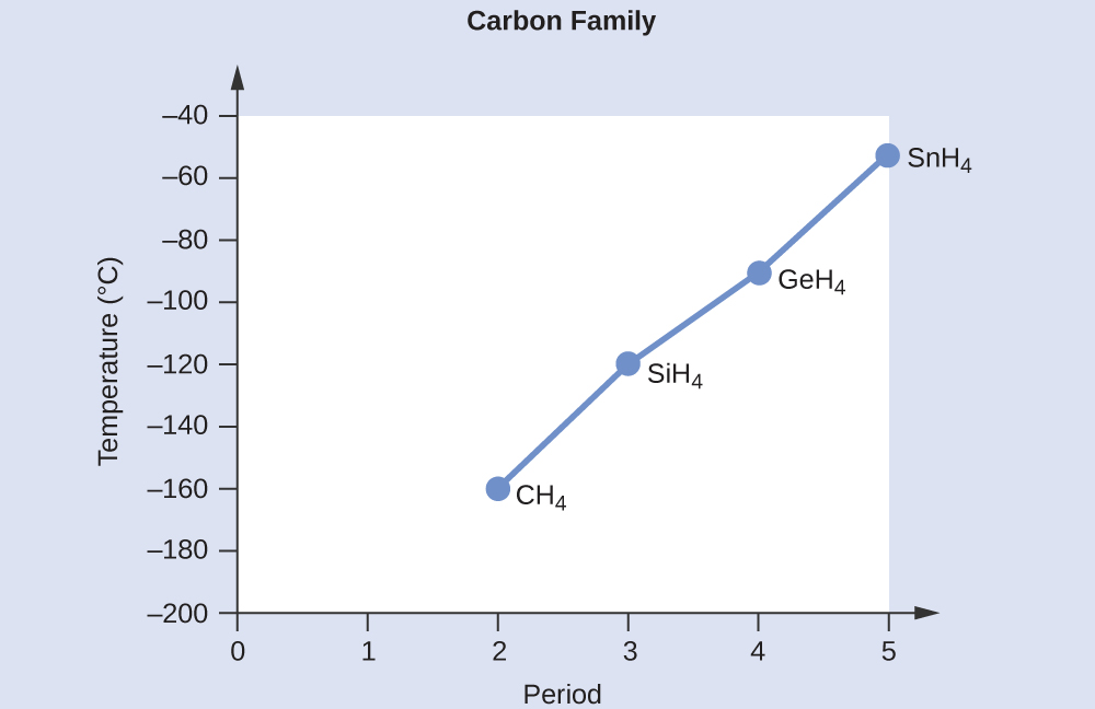
A graph of the actual boiling points of these compounds versus the period of the group 14 element shows this prediction to be correct.
Check Your Learning
Order the following hydrocarbons from lowest to highest boiling point: C2H6, C3H8, and C4H10.
Answer
C2H6 < C3H8 < C4H10. All of these compounds are nonpolar and only have London dispersion forces: the larger the molecule, the larger the dispersion forces and the higher the boiling point. The ordering from lowest to highest boiling point is therefore C2H6 < C3H8 < C4H10.
Example 2: Effect of Shape on London Forces and Boiling Points
As seen previously, the shapes of molecules also affect the magnitudes of the dispersion forces between them. Above, we compared the isomers isopentane, n-pentane, and neopentane and ranked the strength of their IMFs. The boiling points of these isomers are 9.5 °C, 27 °C and 36 °C, in no particular order. Using what you know about how London forces are affected by the shape of a molecule, determine which boiling point corresponds to which isomer. Explain how you came to your conclusions. It may be useful to revisit the structures.
Solution
We saw above that n-pentane has the most elongated structure and that this increased surface area available for contact between molecules resulted in a stronger London force. Therefore, we would predict that n-pentane has the highest boiling point of 36 °C due to its strong dispersion forces. Since neopentane molecules are the most compact of the three and have the least available surface area for intermolecular contact, we would predict that this molecule would have a boiling point of 9.5 °C. This means that isopentane, having an intermediate surface area, would have a boiling point of 27 °C.
Now let’s compare two molecules with the same number of atoms and similar molecular weight, HCl and F2. Both of these molecules experience London forces, but only HCl has a dipole moment and would therefore experience dipole-dipole interactions. The higher normal boiling point (the boiling point at 1 atm) of HCl (188 K) compared to F2 (85 K) is a reflection of the greater strength of dipole-dipole attractions between HCl molecules, compared to the attractions between nonpolar F2 molecules. We will often use values such as boiling or freezing points, or enthalpies of vaporization or fusion, as indicators of the relative strengths of IMFs of attraction present within different substances.
However, dipole-dipole interactions do not definitively indicate a higher boiling point. Consider the trends in boiling points for the binary hydrides of group 15 (NH3, PH3, AsH3, and SbH3), group 16 hydrides (H2O, H2S, H2Se, and H2Te), and group 17 hydrides (HF, HCl, HBr, and HI). The boiling points of the heaviest three hydrides for each group are plotted in Figure 8.
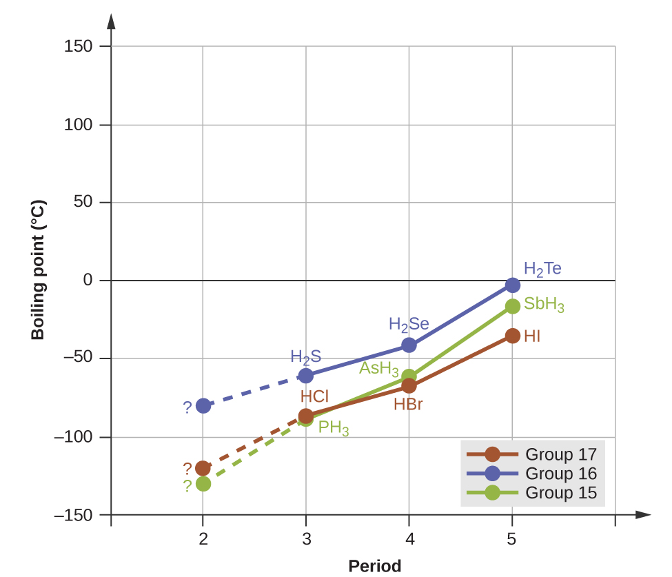
As we progress down any of these groups, the polarities of the molecules decrease slightly, whereas the sizes of the molecules increase substantially. The effect of increasingly stronger dispersion forces dominates that of increasingly weaker dipole-dipole attractions, and the boiling points are observed to increase steadily.
Example 3: Dipole-Dipole Forces and Their Effects
Predict which will have the higher boiling point: N2 or CO. Explain your reasoning.
Solution
CO and N2 are both diatomic molecules with same number of electrons, so they experience similar London dispersion forces. Because CO is a polar molecule, it also experiences dipole-dipole attractions. Because N2 is nonpolar, its molecules cannot exhibit dipole-dipole attractions. The additional dipole-dipole attractions between CO molecules leads to CO having the higher boiling point.
Check Your Learning
Predict which will have the higher boiling point: ICl or Br2. Explain your reasoning.
Answer
ICl (iodine monochloride). ICl and Br2 have similar number of electrons and therefore experience similar London dispersion forces. ICl is polar and thus also exhibits dipole-dipole attractions; Br2 is nonpolar and does not. The additional dipole-dipole attractions require more energy to overcome, so ICl will have the higher boiling point.
The Effect of Hydrogen Bonding on Boiling Point
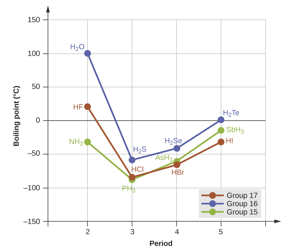
Hydrogen bonds a special type of interaction that occurs between an H atom attached to an N, O, or F atom on one molecule and the lone pairs on another N, O, or F atom on another molecule. If we use the trend in Figure 8 above to predict the boiling points for the lightest hydride for each group, we would expect NH3 to boil at about -120 °C, H2O to boil at about -80 °C, and HF to boil at about -110 °C. However, when we measure the boiling points for these compounds, we find that they are dramatically higher than the trends would predict, as shown in Figure 9. The stark contrast between our naïve predictions and reality provides compelling evidence for the strength of hydrogen bonding.
Example 4: Effect of Hydrogen Bonding on Boiling Points
Consider the compounds dimethylether (CH3OCH3), ethanol (CH3CH2OH), and propane (CH3CH2CH3). Their boiling points, not necessarily in order, are −42.1 °C, −24.8 °C, and 78.4 °C. Match each compound with its boiling point. Explain your reasoning.
Solution
The VSEPR-predicted shapes of CH3OCH3, CH3CH2OH, and CH3CH2CH3 are similar, as are their number of electrons, so they will exhibit similar dispersion forces. Since CH3CH2CH3 is nonpolar, it will exhibit only London dispersion forces. Because CH3OCH3 is polar, it will also experience dipole-dipole attractions. Finally, CH3CH2OH has an −OH group, and so it will furthermore experience hydrogen bonding. So the ordering in terms of strength of IMFs, and thus boiling points, is CH3CH2CH3 < CH3OCH3 < CH3CH2OH. The boiling point of propane is −42.1 °C, the boiling point of dimethylether is −24.8 °C, and the boiling point of ethanol is 78.5 °C.
Check Your Learning
Ethane (CH3CH3) has a melting point of −183 °C and a boiling point of −89 °C. Predict the melting and boiling points for methylamine (CH3NH2). Explain your reasoning.
Answer
The melting point and boiling point for methylamine are predicted to be significantly greater than those of ethane. CH3CH3 and CH3NH2 are similar in size, but methylamine possesses an −NH group and therefore may exhibit hydrogen bonding. This greatly increases its IMFs, and therefore its melting and boiling points. It is difficult to predict values, but the known values are a melting point of −93 °C and a boiling point of −6 °C.
