
D21.3 Voltaic Cells
A voltaic cell (or galvanic cell) is an electrochemical cell in which a spontaneous redox reaction produces an electric current. Consider what happens when a clean piece of copper metal is placed in a solution of silver nitrate.
When the copper metal contacts the silver nitrate solution, silver metal begins to form on the copper surface and Cu2+ ions pass into the solution (indicated by the blue-green color of the solution). The net ionic equation for the reaction is:
which may be split into its two half-reactions that sum to the overall reaction:
| Oxidation: | Cu(s) | ⟶ | Cu2+(aq) + 2 e‾ |
| Reduction: | 2 Ag+(aq) + 2 e‾ | ⟶ | 2 Ag(s) |
The half-reactions make clear that two electrons are transferred from a copper atom, which forms a Cu2+ ion. Each of the two electrons is then transferred to one Ag+ ion, which forms a silver atom. Because a flow of electrons constitutes an electric current, this electron transfer can generate an electric current if we devise a way to carry out the two half-reactions in separate vessels and connect them with a metal (electrically conductive) wire. This is in essence how a voltaic cell is designed. Figure: Voltaic Cell shows one way to do this.
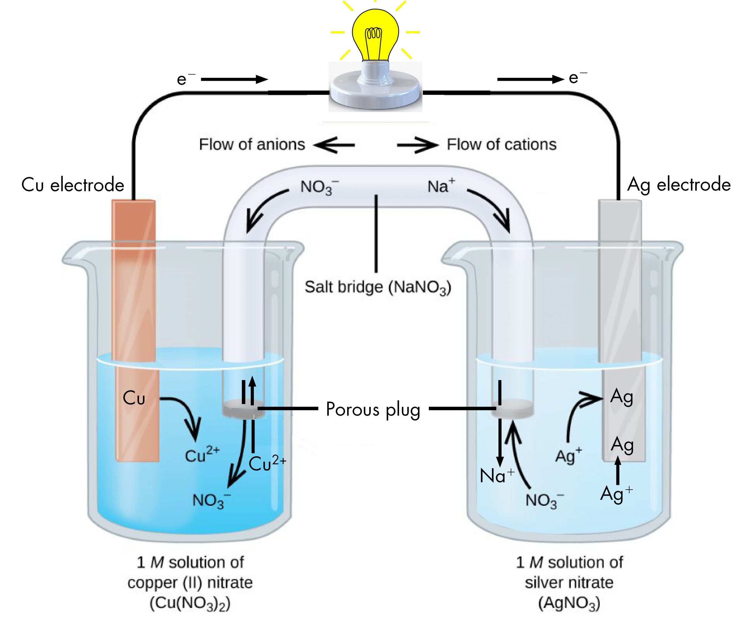
The beaker on the left contains a 1-M solution of copper(II) nitrate [Cu(NO3)2] with a strip of copper metal partially submerged in the solution. The copper strip is an electrode, a means for conducting electrons into or out of the solution. At the surface of the copper strip, the oxidation half-reaction occurs:
The flow of electrons (electric current) passes out of the solution via the copper strip, flows through the light bulb, and moves into the silver strip in the beaker on the right. In the right-hand beaker, the reduction half-reaction occurs near the surface of the silver strip:
Thus, with the two half-reactions occurring in separate beakers, an electric current can be generated. The container in which each half-reactions occurs is called a half-cell.
If this were all that happened, the electric current would not flow for long. In the left-hand beaker, one Cu2+ ion is added to the solution for every two electrons conducted into the external wire. This means that the solution is continuously accumulating excess positive ions as the reaction occurs and an electric charge is building up. Such a charge build up would prevent further oxidation reaction from occurring. This can be mitigated if some positive ions move out of the beaker or some negative ions move into the beaker. A similar issue is occurring in the right-hand beaker, where Ag+ ions are being removed from the solution. Balancing total ionic charges requires either negative ions move out of the right-hand solution or positive ions move in.
This balancing of ion charges in the two separated half-reactions is maintained by the salt bridge, a solution of a salt that does not mix with either half-cell solution but allows ions to pass into or out of the half-cells. By allowing ions to conduct charge into or out of the half-cells, the salt bridge completes the electrical circuit involving the two half-cells. Without it, current cannot flow for more than an instant. Notice that negative ions in the salt bridge move in the same direction as electrons around the circuit (clockwise in the above figure) and positive ions move in the opposite direction.
The half-cell in which oxidation occurs is called the anode. The half-cell in which reduction occurs is called the cathode. It is easy to remember that the anode involves oxidation because both words begin with a vowel. It is easy to remember that the cathode involves reduction because both words begin with a consonant. These definitions, anode/oxidation and cathode/reduction, are true for any electrochemical cell, not just a voltaic cell.
Exercise: Reactions for a Voltaic Cell
Voltaic Cell Potential
When a voltaic cell is connected to a load, such as a light bulb, an electric current flows because there is a difference in electrical potential between the two electrodes. That electrical potential difference can be measured using a potentiometer (a voltmeter).
The voltaic cell shown below involves the spontaneous reaction:
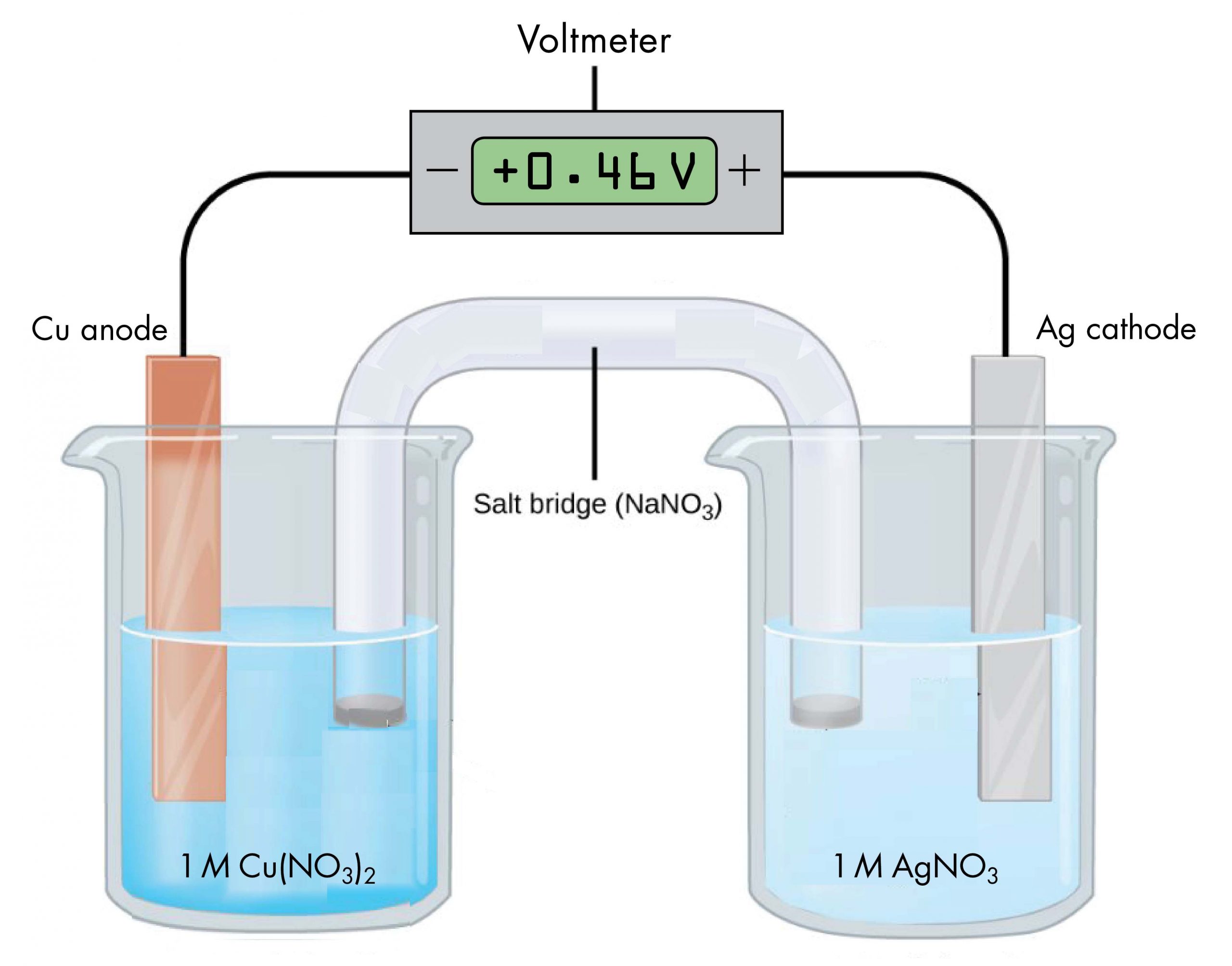
According to the reaction equation, copper loses electrons and is oxidized to copper(II) ions, so the half-cell with the copper electrode is the anode. According to the reaction equation, silver ions gain electrons and are reduced to silver, so the half-cell with the silver electrode is the cathode. The copper electrode has a more negative potential than the silver electrode.
When the more negative copper electrode is connected to the negative terminal of the voltmeter and the more positive silver electrode is connected to the positive terminal of the voltmeter, the meter reads +0.46 V. This reading is called the cell potential, Ecell. It is a measure of the energy per unit charge available from a redox reaction (V = J/C). A positive cell potential indicates how much electrical work a spontaneous reaction in a voltaic cell can do per unit electric charge moving though the circuit.
Under standard-state conditions (1 bar or 1 M), the cell potential is the standard cell potential, E°cell (pronounced “E-standard-cell”). Thus, based on the voltmeter reading in the figure above, E°cell = 0.46 V.
A voltmeter measures the difference in electrical potential between its positive terminal and its negative terminal. Because the positive meter terminal is on the right in the figure above, the cell potential is the difference in electrical potential between the right-hand half-cell and the left-hand half-cell, and we can write:
In the above figure, all concentrations are 1 M (standard-state conditions), so we can also write,
If the wire connections are reversed, a typical voltmeter would read −0.46 V. This provides an experimental way to determine which half-cell is the cathode and which is the anode: a positive voltmeter reading indicates that the meter’s negative terminal is connected to the anode and the positive terminal is connected to the cathode; a negative voltmeter reading indicates the negative terminal is connected to the cathode and the positive terminal is connected to the anode.
The cell potential of a voltaic cell depends on the substances in each half-cell and the concentrations of solutions and partial pressures of gases involved in the half-cell. A salt bridge must be present to complete an electric circuit. In the salt bridge when the cell generates electric current, anions move toward the anode and cations move toward the cathode.
Exercise: Voltaic Cell Terminology
Cell Notation
Drawing a pictorial diagram, like the figure below, to define a voltaic cell takes a lot of time. Cell notation is an abbreviation that summarizes the important information about a voltaic cell. In cell notation, a vertical line, |, denotes a phase boundary and a double line, ||, a salt bridge. The anode electrode is written to the left, followed by the anode solution, then the salt bridge, then the cathode solution, and, finally, the cathode electrode to the right. Figure: Cell Notation below shows how the cell notation for a voltaic cell relates to various components of the cell.
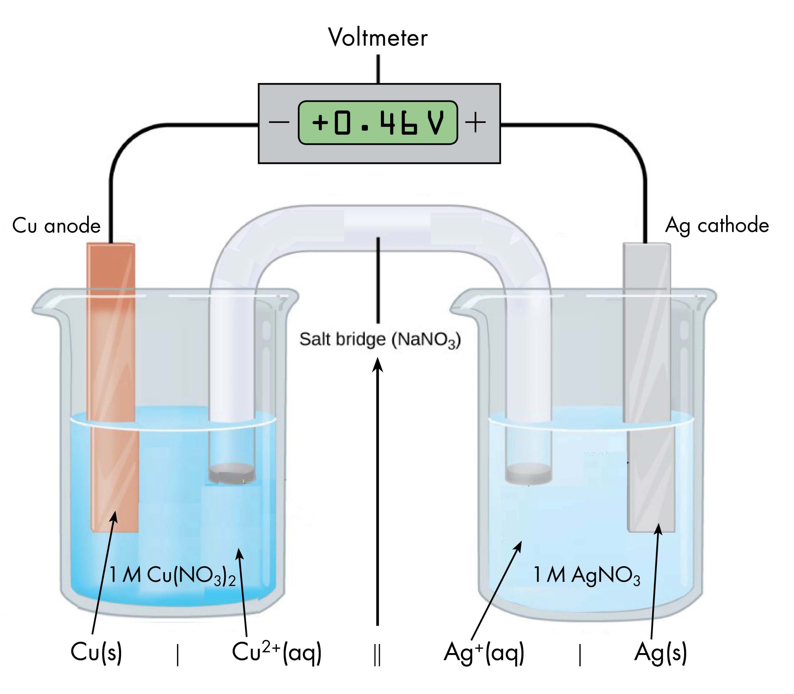
Note that spectator ions, such as NO3−, are not included in the cell notation, and if there are coefficients in a half-reaction, the coefficients are not included (that is, the coefficients of 2 in the silver half-reaction do not appear in the cell notation). When known, the initial concentrations of ions are usually included in the cell notation, so a more complete cell notation for the cell above is Cu(s) | Cu2+(aq, 1 M) || Ag+(aq, 1 M) | Ag(s).
Some redox reactions involve species that are poor conductors of electricity, such as gases or ionic solids. For such substances, an inert electrode that does not participate in the reactions is used. An example of such a voltaic cell is shown below.
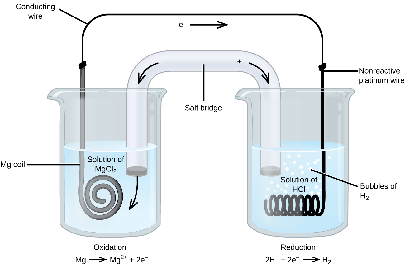
The redox reaction involved is:
| Oxidation (anode): | Mg(s) | ⟶ | Mg2+(aq) + 2e− |
| Reduction (cathode): | 2H+(aq) + 2e− | ⟶ | H2(g) |
| overall: | Mg(s) + 2H+(aq) | ⟶ | Mg2+(aq) + H2(g) |
This voltaic cell uses an inert platinum wire for the cathode, so the cell notation is:
The magnesium electrode is an active electrode because it participates in the redox reaction. Inert electrodes, like the platinum electrode, do not participate in the redox reaction but must be present so that there is a complete electrical circuit. Platinum and gold are among the least reactive metals so they are good choices for inert electrodes. Graphite, also inert to many chemical reactions, is another common option.
Activity: Half-reactions and Cell Notation
Consider a voltaic cell based on this spontaneous reaction:
5Fe2+(aq) + MnO4−(aq) + 8H+(aq) ⟶ 5Fe3+(aq) + Mn2+(aq) + 4H2O(ℓ)
Write the oxidation and reduction half-reactions and use cell notation to describe a voltaic cell based on this reaction. When the cell produces electric current, which reaction occurs at the anode? Which occurs at the cathode?
Write in your notebook, then left-click here for an explanation.
Assigning oxidation numbers to each element in each species in the overall redox reaction shows that Fe2+ undergoes oxidation when one electron is lost to form Fe3+, and MnO4− is reduced as it gains five electrons to form Mn2+.
Thus the balanced half-reactions are
| Oxidation: | 5 × (Fe2+(aq) | ⟶ | Fe3+(aq) + e−) |
| Reduction: | MnO4−(aq) + 8H+(aq) + 5e− | ⟶ | Mn2+(aq) + 4H2O(ℓ) |
When the cell generates electric current, the oxidation half-reaction occurs at the anode and the reduction half-reaction occurs at the cathode.
Cell notation lists the species in each half-cell, starting with the anode. The anode (and the cathode) half-reaction involves only ions in solution so there is no solid-phase metal involved; therefore it is necessary to use an inert electrode, such as platinum, to conduct electrons out of the anode half-cell. Additionally, no concentration information is provided. Hence, the cell notation is
Pt(s) | Fe2+(aq), Fe3+(aq) || MnO4−(aq), H+(aq), Mn2+(aq) | Pt(s)
Exercise: Cell Notation
A historically important voltaic cell is the Daniell cell, a variant of which, the gravity cell, was used to power telegraph communication in the late 19th century. In a Daniell cell, zinc reacts with copper(II) ions to generate electric current.
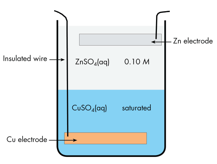
The cell has a copper electrode at the bottom of a jar with an insulated wire connecting it to the outside. The bottom half of the jar contains saturated copper(II) sulfate solution. The upper half of the jar contains dilute zinc sulfate solution, which is less dense than the copper(II) sulfate and can be carefully poured onto the copper(II) sulfate without mixing the solutions. At the top of the zinc sulfate solution is a zinc electrode, suspended from the rim of the jar. Current flows in a wire connecting the copper electrode to the zinc electrode. There is no salt bridge, but ions can move in either direction across the interface between the two solutions.
Write the cell notation for the gravity cell.
Write in your notebook, then left-click here for an explanation.
The cell notation is
Zn(s) | Zn2+(aq) | Cu2+(aq) | Cu(s)
According to the description of the gravity cell zinc reacts with copper(II) ions. Thus, Zn2+ ions and Cu(s) atoms must be produced. Therefore Zn must be oxidized and copper(II) ions must be reduced. The Zn half-cell is the anode and the copper(II) half-cell is the cathode, so the Zn half-cell is written first in the cell notation.
There is no double vertical line because there is no salt bridge. The single vertical line in the middle denotes the interface between the copper(II) sulfate solution below and the zinc sulfate solution above.
Please use this form to report any inconsistencies, errors, or other things you would like to change about this page. We appreciate your comments. 🙂 (Note that we cannot answer questions via the google form. If you have a question, please post it on Piazza.)
