"

18 Catalysts; Connecting Mechanisms to Empirically-Determined Rate Laws; Catalysis; Critiques of Mechanisms (M13Q11)

Learning Objectives

  • Critique a provided reaction mechanism by determining whether it is in agreement with the experimentally determined stoichiometry of a reaction and the experimentally determined rate law.
  • Sketch a reaction profile based on a provided mechanism, or critique a mechanism based on a provided reaction profile.
  • Describe the role of catalysts in reactions, and from overall stoichiometry and the rate law, or from a reaction mechanism, determine whether a catalyst is involved in a reaction.

| Key Concepts and Summary | Key Equations | Glossary | End of Section Exercises |

Catalysts and Reaction Rates

We have seen that the rate of many reactions can be accelerated by catalysts. Catalysts function by providing an alternate reaction mechanism that has a lower activation energy than would be found in the absence of the catalyst. In some cases, the catalyzed mechanism may include additional steps, as depicted in the reaction diagrams shown in Figure 1. This lower activation energy results in an increase in the rate of reaction as described by the Arrhenius equation. Note that a catalyst decreases the activation energy for both the forward and the reverse reactions and hence accelerates both the forward and the reverse reactions. Consequently, the presence of a catalyst will permit a system to reach equilibrium more quickly, but it has no effect on the position of the equilibrium as reflected in the value of its equilibrium constant (see the next chapter on chemical equilibrium).
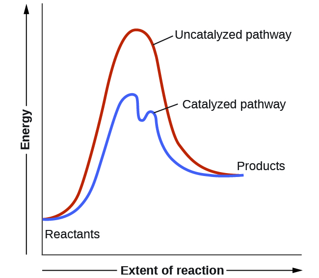
A graph is shown with the label, “Extent of reaction,” appearing in a right pointing arrow below the x-axis and the label, “Energy,” in an upward pointing arrow just left of the y-axis. Approximately one-fifth of the way up the y-axis, a very short, somewhat flattened portion of both a red and a blue curve are shown. This region is labeled “Reactants.” A red concave down curve extends upward to reach a maximum near the height of the y-axis. This curve is labeled, “Uncatalyzed pathway.” From the peak, the curve continues downward to a second horizontally flattened region at a height of about one-third the height of the y-axis. This flattened region is labeled, “Products.” A second curve is drawn in blue with the same flattened regions at the start and end of the curve. The height of this curve is about two-thirds the height of the first curve and just right of its maximum, the curve dips low, then rises back and continues a downward trend at a lower height, but similar to that of the red curve. This blue curve is labeled, “Catalyzed pathway.”
Figure 1. This potential energy diagram shows the effect of a catalyst on the activation energy. The catalyst provides a different reaction path with a lower activation energy. As shown, the catalyzed pathway involves a two-step mechanism (note the presence of two transition states) and an intermediate species (represented by the valley between the two transitions states).

Example 1

Using Reaction Diagrams to Compare Catalyzed Reactions
The two reaction diagrams here represent the same reaction: one without a catalyst and one with a catalyst. Identify which diagram suggests the presence of a catalyst, and determine the activation energy for the catalyzed reaction:
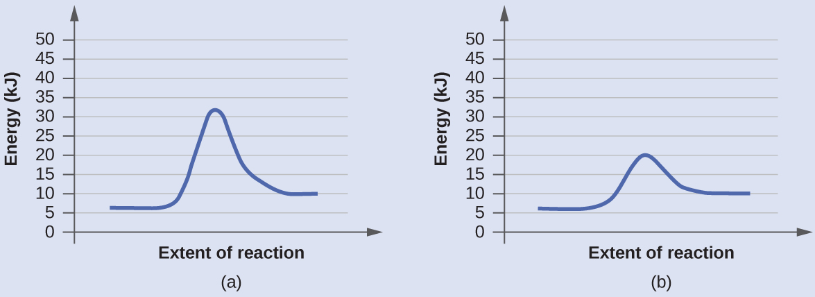
In this figure, two graphs are shown. The x-axes are labeled, “Extent of reaction,” and the y-axes are labeled, “Energy ( k J ).” The y-axes are marked off from 0 to 50 in intervals of five. In a, a blue curve is shown. It begins with a horizontal segment at about 6. The curve then rises sharply near the middle to reach a maximum of about 32 and similarly falls to another horizontal segment at about 10. In b, the curve begins and ends similarly, but the maximum reached near the center of the graph is only 20.

Solution
A catalyst does not affect the energy of reactant or product, so those aspects of the diagrams can be ignored. They are, as we would expect, identical in the two graphs. However, there is a noticeable difference in the energy of the transition state, which is distinctly lower in diagram (b) than it is in (a). This indicates the use of a catalyst in diagram (b). The activation energy is the difference between the energy of the starting reagents and the transition state—a maximum on the reaction coordinate diagram. The reagents are at 6 kJ and the transition state is at 20 kJ, so the activation energy can be calculated as follows:

Ea = 20 kJ – 6 kJ = 14 kJ

Check Your Learning
Determine which of the two diagrams here (both for the same reaction) involves a catalyst, and identify the activation energy for the catalyzed reaction:
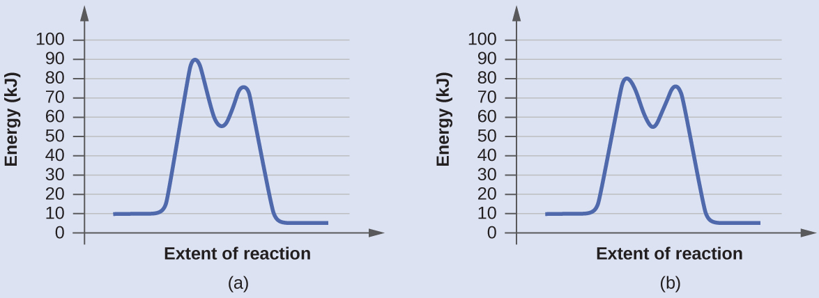
In this figure, two graphs are shown. The x-axes are labeled, “Extent of reaction,” and the y-axes are labeledc “Energy (k J).” The y-axes are marked off from 0 to 100 at intervals of 10. In a, a blue curve is shown. It begins with a horizontal segment at about 10. The curve then rises sharply near the middle to reach a maximum of about 91, then sharply falls to about 52, again rises sharply to about 73 and falls to another horizontal segment at about 5. In b, the curve begins and ends similarly, but the first peak reaches about 81, drops to about 55, then rises to about 77 before falling to the horizontal region at about 5.

Answer:

Diagram (b) is a catalyzed reaction with an activation energy of about 70 kJ.

Science in Real Life: Homogeneous and Heterogenous Catalysts

A homogeneous catalyst is present in the same phase as the reactants. It interacts with a reactant to form an intermediate substance, which then decomposes or reacts with another reactant in one or more steps to regenerate the original catalyst and form product.

As an important illustration of homogeneous catalysis, consider the earth’s ozone layer. Ozone in the upper atmosphere, which protects the earth from ultraviolet radiation, is formed when oxygen molecules absorb ultraviolet light and undergo the reaction:

3O2(g)  [latex]\xrightarrow{h\upsilon}[/latex]  2O3(g)

Ozone is a relatively unstable molecule that decomposes to yield diatomic oxygen by the reverse of this equation. This decomposition reaction is consistent with the following mechanism:

         O3   →   O2  +  O
O  +  O3   →   2 O2        

The presence of nitric oxide, NO, influences the rate of decomposition of ozone. Nitric oxide acts as a catalyst in the following mechanism:

NO(g)  +  O3(g)   →   NO2(g)  +  O2(g)
            O3(g)   →   O2(g)  +  O(g)
NO2(g)  +  O(g)   →   NO(g)  +  O2(g)

The overall chemical change for the catalyzed mechanism is the same as:

2 O3(g)   →   3 O2(g)

The nitric oxide reacts and is regenerated in these reactions. It is not permanently used up; thus, it acts as a catalyst. The rate of decomposition of ozone is greater in the presence of nitric oxide because of the catalytic activity of NO. Certain compounds that contain chlorine also catalyze the decomposition of ozone.

A heterogeneous catalyst is a catalyst that is present in a different phase (usually a solid) than the reactants. Such catalysts generally function by furnishing an active surface upon which a reaction can occur. Gas and liquid phase reactions catalyzed by heterogeneous catalysts occur on the surface of the catalyst rather than within the gas or liquid phase.

Figure 2 illustrates the steps that chemists believe to occur in the reaction of compounds containing a carbon–carbon double bond with hydrogen on a nickel catalyst. Nickel is the catalyst used in the hydrogenation of polyunsaturated fats and oils (which contain several carbon–carbon double bonds) to produce saturated fats and oils (which contain only carbon–carbon single bonds).
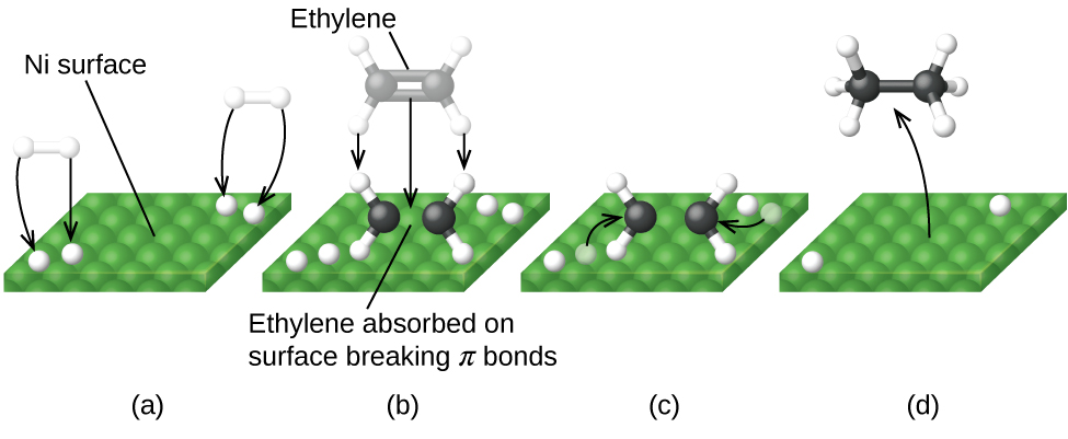
In this figure, four diagrams labeled a through d are shown. In each, a green square surface is shown in perspective to provide a three-dimensional appearance. In a, the label “N i surface” is placed above with a line segment extending to the green square. At the lower left and upper right, pairs of white spheres bonded tougher together appear as well as white spheres on the green surface. Black arrows are drawn from each of the white spheres above the surface to the white sphere on the green surface. In b, the white spheres are still present on the green surface. Near the center of this surface is a molecule with two central black spheres with a double bond indicated by two horizontal black rods between them. Above and below to the left and right, a total of four white spheres are connected to the black spheres with white rods. A line segment extends from this structure to the label, “Ethylene absorbed on surface breaking pi bonds.” Just above this is a nearly identical structure greyed out with three downward pointing arrows to the black and white structure to indicate downward motion. The label “Ethylene” at the top of the diagram is connected to the greyed out structure with a line segment. In c, the diagram is very similar to b except that the greyed out structure and labels are gone and one of the white spheres near the black and white structure in each pair on the green surface is greyed out. Arrows point from the greyed out white spheres to the double bond between the two black spheres. In d, only a single white sphere remains from each pair in the green surface. A curved arrow points from the middle of the green surface to a model above with two central black spheres with a single black rod indicating a single bond between them. Each of the black rods has three small white spheres bonded as indicated by white rods between the black spheres and the small white spheres. The four bonds around each black sphere are evenly distributed about the black spheres.
Figure 2. There are four steps in the catalysis of the reaction C2H+  H2   ⟶  C2H6 by nickel. (a) Hydrogen is adsorbed on the surface, breaking the H–H bonds and forming Ni–H bonds. (b) Ethylene is adsorbed on the surface, breaking the π-bond and forming Ni–C bonds. (c) Atoms diffuse across the surface and form new C–H bonds when they collide. (d) C2H6 molecules escape from the nickel surface, since they are not strongly attracted to nickel.

Science in Real Life: Enzyme Structure and Function

The study of enzymes is an important interconnection between biology and chemistry. Enzymes are usually proteins (polypeptides) that help to control the rate of chemical reactions between biologically important compounds, particularly those that are involved in cellular metabolism.

Enzyme molecules possess an active site, a part of the molecule with a shape that allows it to bond to a specific substrate (a reactant molecule), forming an enzyme-substrate complex as a reaction intermediate. There are two models that attempt to explain how this active site works. The most simplistic model is referred to as the lock-and-key hypothesis, which suggests that the molecular shapes of the active site and substrate are complementary, fitting together like a key in a lock. The induced fit hypothesis, on the other hand, suggests that the enzyme molecule is flexible and changes shape to accommodate a bond with the substrate. This is not to suggest that an enzyme’s active site is completely malleable, however. Both the lock-and-key model and the induced fit model account for the fact that enzymes can only bind with specific substrates, since in general a particular enzyme only catalyzes a particular reaction (Figure 3).
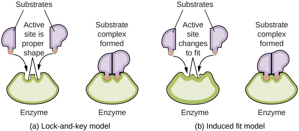
A diagram is shown of two possible interactions of an enzyme and a substrate. In a, which is labeled “Lock-and-key,” two diagrams are shown. The first shows a green wedge-like shape with two small depressions in the upper surface of similar size, but the depression on the left has a curved shape, and the depression on the right has a pointed shape. This green shape is labeled “Enzyme.” Just above this shape are two smaller, irregular, lavender shapes each with a projection from its lower surface. The lavender shape on the left has a curved projection which matches the shape of the depression on the left in the green shape below. This projection is shaded orange and has a curved arrow extending from in to the matching depression in the green shape below. Similarly, the lavender shape on the right has a projection with a pointed tip which matches the shape of the depression on the right in the green shape below. This projection is shaded orange and has a curved arrow extending from in to the matching depression in the green shape below. Two line segments extend from the depressions in the green shape to form an inverted V shape above the depressions. Above this and between the lavender shapes is the label, “Active site is proper shape.” The label “Substrates” is at the very top of the diagram with line segments extending to the two lavender shapes. To the right of this diagram is a second diagram showing the lavender shapes positioned next to each other, fit snugly into the depressions in the green shape, which is labeled “Enzyme.” Above this diagram is the label, “Substrate complex formed.” In b, which is labeled “Induced fit,” two diagrams are shown. The first shows a green wedge-like shape with two small depressions in the upper surface of similar size, but irregular shape. This green shape is labeled “Enzyme.” Just above this shape are two smaller irregular lavender shapes each with a projection from its lower surface. The lavender shape on the left has a curved projection. This projection is shaded orange and has a curved arrow extending from it to the irregular depression just below it in the green shape below. Similarly, the lavender shape on the right has a projection with a pointed tip. This projection is shaded orange and has a curved arrow extending from it to the irregular depression just below it in the green shape below. Two line segments extend from the depressions in the green shape to form an inverted V shape above the depressions. Above this and between the lavender shapes is the label, “Active site changes to fit.” The label, “Substrates” is at the very top of the diagram with line segments extending to the two lavender shapes. To the right of this diagram is a second diagram showing the purple shapes positioned next to each other, fit snugly into the depressions in the green shape, which is labeled “Enzyme.” Above this diagram is the label “Substrate complex formed.” The projections from the lavender shapes match the depression shapes in the green shape, resulting in a proper fit.
Figure 3. (a) According to the lock-and-key model, the shape of an enzyme’s active site is a perfect fit for the substrate. (b) According to the induced fit model, the active site is somewhat flexible, and can change shape in order to bond with the substrate.

Key Concepts and Summary

To begin this chapter, we looked at the four factors that can influence the rate of the reaction. We use rate laws to see concentration’s and phase’s effect and we can use the Arrhenius equation to see how temperature affects the rate (through the rate constant). In this section, catalyst’s effect on the activation energy is studied. By changing the mechanism and lowering the activation energy, catalysts always increase the rate of a reaction. If the concentration of the catalyst is not included in the rate law, the catalyst changes the rate constant.

Glossary

heterogeneous catalyst
a catalyst present in a different phase than the reactants

homogeneous catalyst
a catalyst present in the same phase as the reactants

Chemistry End of Section Exercises

  1. Account for the increase in reaction rate brought about by a catalyst.
  2. Consider this scenario and answer the following questions: Chlorine atoms resulting from decomposition of chlorofluoromethanes, such as CCl2F2, catalyze the decomposition of ozone in the atmosphere. One simplified mechanism for the decomposition is:
    O3 → O2 + O
    O3 + Cl → O2 + ClO
    ClO + O → Cl +O2
    1. Explain why chlorine atoms are catalysts.
    2. Is ClO a catalyst?

Answers to Chemistry End of Section Exercises

  1. The general mode of action for a catalyst is to provide a mechanism by which the reactants can unite more readily by taking a path with a lower reaction energy.
    1. Chlorine atoms are a catalyst because they react in the second step but are regenerated in the third step. Thus, they are not used up, which is a characteristic of catalysts.
    2. No, ClO is an intermediate, not a catalyst. It is created in step 2 and used is step 3.

License

Icon for the Creative Commons Attribution-NonCommercial-ShareAlike 4.0 International License

CHEM 104: Working Copy Copyright © by Chem 104 Textbook Team is licensed under a Creative Commons Attribution-NonCommercial-ShareAlike 4.0 International License, except where otherwise noted.

Feedback/Errata

Leave a Reply

Your email address will not be published. Required fields are marked *