
Additional Reading Materials
Chapter 6: Molecular Structures
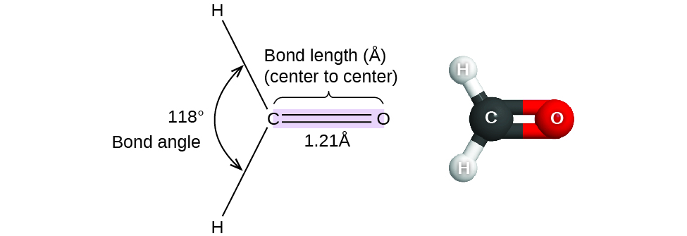
Thus far, we have used two-dimensional Lewis structures to represent molecules. However, molecular structure is actually three-dimensional, and it is important to be able to describe molecular bonds in terms of their distances, angles, and relative arrangements in space (Figure 1). A bond angle is the angle between any two bonds that include a common atom, usually measured in degrees. A bond distance (or bond length) is the distance between the nuclei of two bonded atoms along the straight line joining the nuclei. Bond distances are measured in Ångstroms (1 Å = 10–10 m) or picometers (1 pm = 10–12 m, 100 pm = 1 Å).
Ch6.1 VSEPR Theory
Valence shell electron-pair repulsion theory (VSEPR theory) enables us to predict the molecular structure, including approximate bond angles around a central atom, from the number of bonds and lone pairs in a molecule’s Lewis structure. The VSEPR model assumes that electron pairs in the valence shell of a central atom will adopt an arrangement that minimizes repulsions between these electron pairs by maximizing the distance between them. The electrons in the valence shell of a central atom form either bonding pairs of electrons, located primarily between bonded atoms, or lone pairs. The electrostatic repulsion of these electrons is reduced when the various regions of high electron density assume positions as far from each other as possible.
We should understand, however, that the theory only considers electron-pair repulsions. Other interactions, such as nuclear-nuclear repulsions and nuclear-electron attractions, are also involved in the final arrangement that atoms adopt in a particular molecular structure.
As a simple example of VSEPR theory, let us predict the structure of a gaseous BeF2 molecule. The Lewis structure of BeF2 (Figure 2) shows only two electron pairs around the central beryllium atom. With two bonds and no lone pairs of electrons on the central atom, the bonds are as far apart as possible, and the electrostatic repulsion between these regions of high electron density is reduced to a minimum when they are on opposite sides of the central atom. The bond angle is 180°.

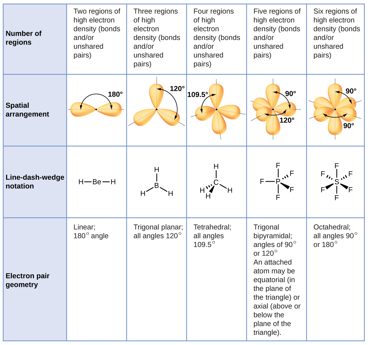
Figure 3 illustrates this and other electron-pair geometries that minimize the repulsions among regions of high electron density (bonds and/or lone pairs). Two regions of electron density around a central atom in a molecule form a linear geometry; three regions form a trigonal planar geometry; four regions form a tetrahedral geometry; five regions form a trigonal bipyramidal geometry; and six regions form an octahedral geometry.
Ch6.2 VSEPR: Electron-Region Geometry versus Molecular Structure
It is important to note that electron-region geometry around a central atom is not the same thing as its molecular structure. The electron-region geometries describe all regions where electrons are located, bonds as well as lone pairs. Molecular structure describes the location of the atoms, not the electrons. We differentiate between these two situations by naming the geometry that includes all electron pairs the electron-region geometry. The structure that includes only the placement of the atoms in the molecule is called the molecular structure. The electron-region geometries will be the same as the molecular structures when there are no lone pairs around the central atom, but they will be different when there are lone pairs present on the central atom.
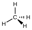
For example, methane, CH4, which is the major component of natural gas, has four bonding pairs of electrons around the central carbon atom; the electron-region geometry is tetrahedral, as is the molecular structure (Figure 4). VSEPR structures like this one are drawn using the wedge and dash notation, in which solid lines represent bonds in the plane of the page, solid wedges represent bonds coming up out of the plane, and dashed lines represent bonds going down into the plane.
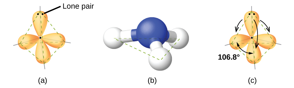
Ammonia, NH3, also has four electron pairs associated with the central nitrogen atom, and thus has a tetrahedral electron-region geometry. One of these regions, however, is a lone pair, which is not included in the molecular structure, and this lone pair influences the shape of the molecule (Figure 5).
Small distortions from the ideal angles can result from differences in repulsion between various regions of electron density. VSEPR theory predicts these distortions by establishing an order of electron-region repulsions, which from greatest to least repulsion is:
lone pair-lone pair > lone pair-bonding pair > bonding pair-bonding pair
This order determines the amount of space occupied by different regions of electrons. A lone pair of electrons occupies a larger region of space than the electrons in a triple bond; in turn, electrons in a triple bond occupy more space than those in a double bond, and so on. The order of sizes from largest to smallest is:
lone pair > triple bond > double bond > single bond
Consider formaldehyde, H2CO, which is used as a preservative for biological and anatomical specimens. This molecule has regions of high electron density that consist of two single bonds and one double bond. The basic geometry is trigonal planar with ideal 120° bond angles, but the double bond causes slightly larger angles (121°), and the angle between the single bonds is slightly smaller (118°).
The ammonia molecule is arranged in a three-dimensional trigonal pyramid shape with the nitrogen atom at the apex and the three hydrogen atoms forming the base. The ideal bond angles in a trigonal pyramid are based on the tetrahedral geometry. Because the lone pair-bonding pair repulsion is greater than the bonding pair-bonding pair repulsion, the H–N–H bond angles in NH3 are slightly smaller than the ideal 109.5° angle. Figure 6 illustrates the molecular structures, which are predicted based on the electron-region geometries for various combinations of lone pairs and bonding pairs.
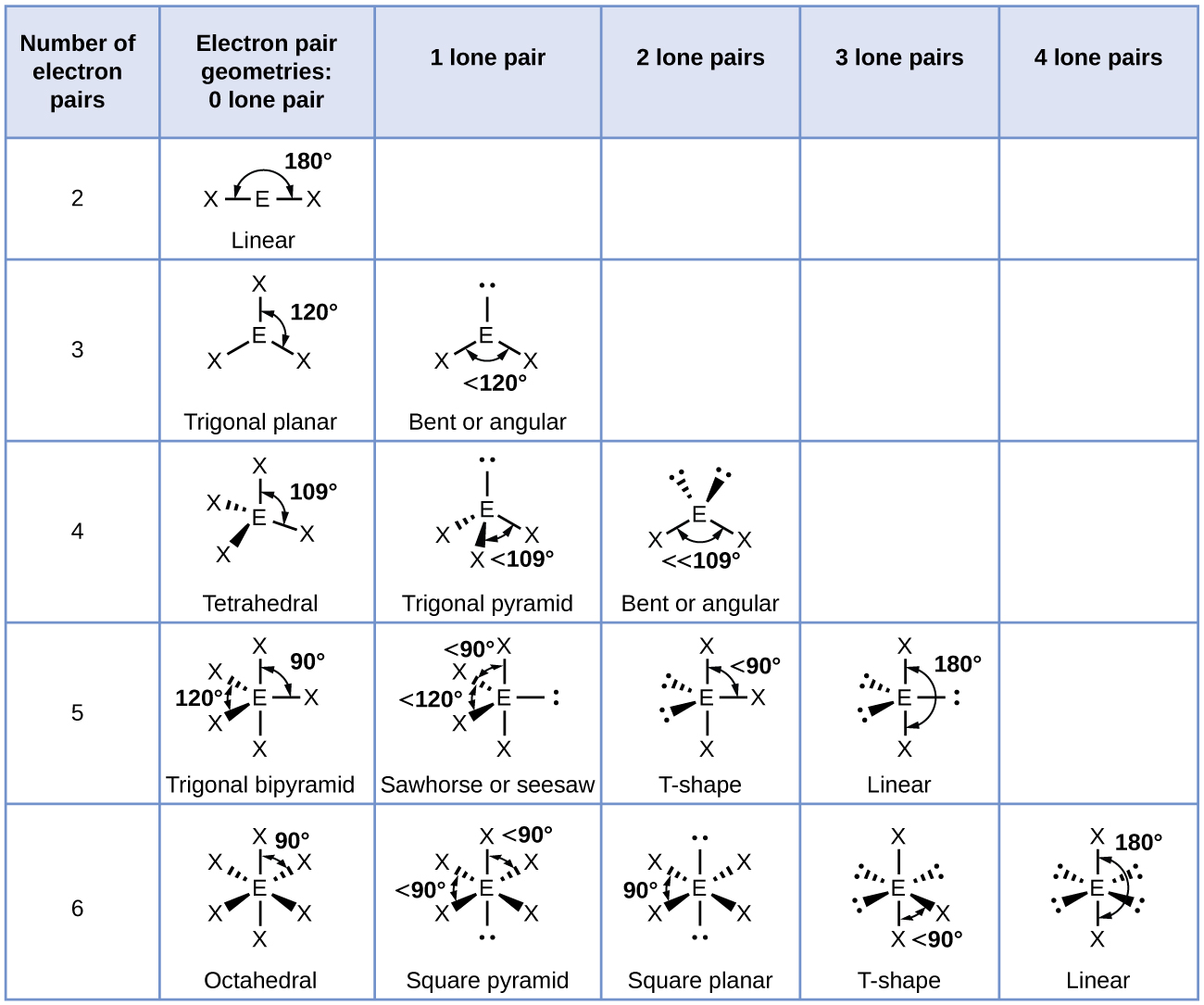
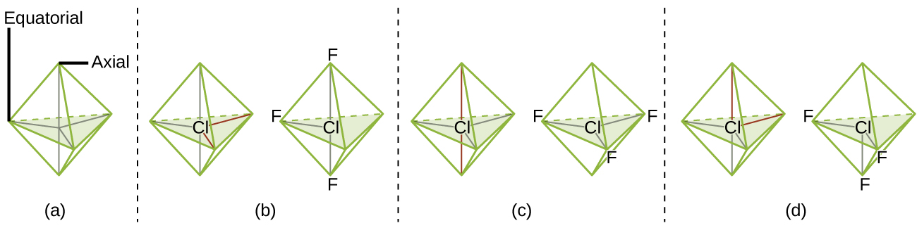
The terminal atom locations (Xs in Figure 6) are equivalent within the linear, trigonal planar, and tetrahedral electron-region geometries (the first three rows of the table). It does not matter which X is replaced with a lone pair because the molecules can be rotated to convert positions. For trigonal bipyramidal geometries, there are two distinct X positions, as shown in Figure 7: an axial position (if we hold a model of a trigonal bipyramid by the two axial positions, we have an axis around which we can rotate the model) and an equatorial position (three positions form an equator around the middle of the molecule). As shown in Figure 7, the axial position is surrounded by bond angles of 90°, whereas the equatorial position has more space available because of the 120° bond angles. In a trigonal bipyramidal electron-region geometry, lone pairs always occupy equatorial positions because these more spacious positions can more easily accommodate the larger lone pairs.
Theoretically, we can come up with three possible arrangements for the three bonds and two lone pairs for the ClF3 molecule (Figure 7). The stable structure is the one that puts the lone pairs in equatorial locations, giving a T-shaped molecular structure.
When a central atom has two lone electron pairs and four bonding regions, we have an octahedral electron-region geometry. The two lone pairs are on opposite sides of the octahedron (180° apart), giving a square planar molecular structure that minimizes lone pair-lone pair repulsions.
Predicting Electron-Region Geometry and Molecular Structure
The following procedure uses VSEPR theory to determine the electron-region geometries and the molecular structures:
- Write the Lewis structure of the molecule.
- Count the number of regions of electron density (lone pairs and bonds) around the central atom. A single, double, or triple bond counts as one region of electron density.
- Identify the electron-region geometry based on the number from (2).
- Use the number of lone pairs to determine the molecular structure.
Example 1
Predicting Electron-region Geometry and Molecular Structure: CO2 and BCl3
Carbon dioxide, CO2, a molecule produced by the combustion of fossil fuels. Boron trichloride, BCl3, an important industrial chemical.
Solution
(a) We write the Lewis structure of CO2 as:
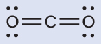
This shows us two regions of high electron density around the carbon atom—each double bond counts as one region, and there are no lone pairs on the carbon atom. VSEPR theory predicts that the two regions of electron density arrange themselves on opposite sides of the central atom with a bond angle of 180°. The electron-region geometry and molecular structure are identical, and a CO2 molecule is linear.
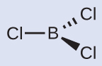
(b) We write the Lewis structure of BCl3 as:
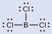
Thus we see that BCl3 contains three single bonds, and there are no lone pairs of electrons on boron. The arrangement of three regions of high electron density gives a trigonal planar electron-region geometry. The B–Cl bonds lie in a plane with 120° angles between them. BCl3 also has a trigonal planar molecular structure.
You can draw all three σ bonds in plane of the paper, rather than using wedge and dash as shown above. But be sure to clearly indicate the 120° angles in a trigonal planar geometry.
Check Your Learning
Carbonate, CO32−, is a common polyatomic ion found in various materials from eggshells to antacids. What are the electron-region geometry and molecular structure of this polyatomic ion?
Answer:
From any one of the three major resonance structures of CO32−: the electron-region geometry is trigonal planar and the molecular structure is trigonal planar.
Example 2
Predicting Electron-region Geometry and Molecular Structure: Ammonium
Two of the top 50 chemicals produced in the United States, ammonium nitrate and ammonium sulfate, both used as fertilizers, contain the ammonium ion, NH4+.
Solution
We write the Lewis structure of NH4+ as:
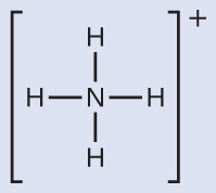
We can see that NH4+ contains four single bonds from the nitrogen atom to hydrogen atoms and no lone pairs. We expect the four regions of high electron density to arrange themselves so that they point to the corners of a tetrahedron with the central nitrogen atom in the middle. Therefore, the electron-region geometry of NH4+ is tetrahedral, and the molecular structure is also tetrahedral.
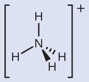
Make sure that you can properly use the wedge and dash notation to depict a correct tetrahedral arrangement.
Check Your Learning
Identify a molecule with trigonal bipyramidal molecular structure.
Answer:
Any molecule with five electron regions around the central atoms with no lone pairs will be trigonal bipyramidal. PF5 is a common example.
Example 3
Predicting Electron-region Geometry and Molecular Structure: Lone Pairs on the Central Atom
Predict the electron-region geometry and molecular structure of a water molecule.
Solution
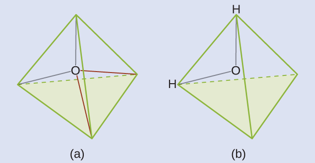
The Lewis structure of H2O indicates that there are four regions of high electron density around the oxygen atom: two lone pairs and two single bonds:
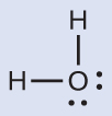
We predict that these four regions are arranged in a tetrahedral geometry (Figure 8). Thus, the electron-region geometry is tetrahedral and the molecular structure is bent with an angle slightly less than 109.5°. In fact, the bond angle is 104.5°.
Check Your Learning
The hydronium ion, H3O+, forms when acids are dissolved in water. Predict the electron-region geometry and molecular structure of this cation.
Answer:
electron-region geometry: tetrahedral; molecular structure: trigonal pyramidal
Example 4
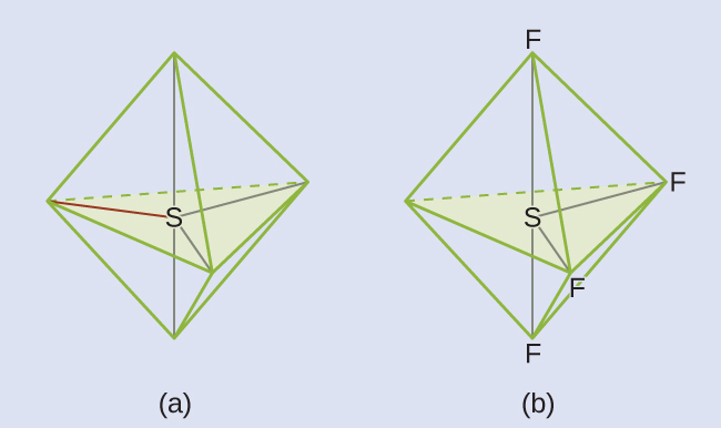
Predicting Electron-region Geometry and Molecular Structure: SF4
Sulfur tetrafluoride, SF4, is extremely valuable for the preparation of fluorine-containing compounds used as herbicides (i.e., SF4 is used as a fluorinating agent).
Solution
The Lewis structure of SF4 indicates five regions of electron density around the sulfur atom: one lone pair and four single bonds:
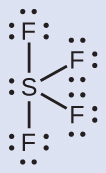
We expect these five regions to adopt a trigonal bipyramidal electron-region geometry. To minimize lone pair repulsions, the lone pair occupies one of the equatorial positions. The molecular structure (Figure 9) is that of a seesaw.
Check Your Learning
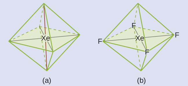
Predict the electron-region geometry and molecular structure of XeF2.
Answer:
The electron-region geometry is trigonal bipyramidal. The molecular structure is linear.
Example 5
Predicting Electron-region Geometry and Molecular Structure: XeF4
Of all the noble gases, xenon is the most reactive, frequently reacting with elements such as oxygen and fluorine.
Solution
The Lewis structure of XeF4 indicates six regions of high electron density around the xenon atom: two lone pairs and four single bonds:
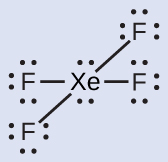
These six regions adopt an octahedral arrangement, which is the electron-region geometry. To minimize repulsions, the lone pairs should be on opposite sides of the central atom (Figure 10). The five atoms are all in the same plane and have a square planar molecular structure.
Check Your Learning
In a certain molecule, the central atom has three lone pairs and two single bonds. What will the electron pair geometry and molecular structure be?
Answer:
electron pair geometry: trigonal bipyramidal; molecular structure: linear
Ch6.3 Molecular Structure for Multicenter Molecules
Larger molecules do not have a single central atom, but are connected by a chain of interior atoms that each possess a “local” geometry. The way these local structures are oriented with respect to each other influences the overall molecular shape.
Example 6
Predicting Structure in Multicenter Molecules
The Lewis structure for the simplest amino acid, glycine, H2NCH2CO2H, is shown here. Predict the local geometry for the nitrogen atom, the two carbon atoms, and the oxygen atom with a hydrogen atom attached:

Solution
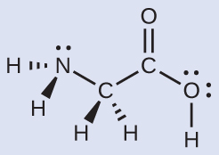
Consider each central atom independently. The electron-region geometries:
- nitrogen––four regions of electron density; tetrahedral
- carbon (CH2)––four regions of electron density; tetrahedral
- carbon (CO2H)—three regions of electron density; trigonal planar
- oxygen (OH)—four regions of electron density; tetrahedral
The local structures:
- nitrogen––three single bonds, one lone pair; trigonal pyramidal
- carbon (CH2)—four single bonds, no lone pairs; tetrahedral
- carbon (CO2)—three bonds (one double and two single), no lone pairs; trigonal planar
- oxygen (OH)—two single bonds, two lone pairs; bent (109°)
Check Your Learning
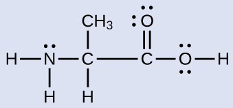
Another amino acid is alanine, which has the Lewis structure shown here. Predict the electron-region geometry and local structure of the nitrogen atom, the three carbon atoms, and the oxygen atom with hydrogen attached:
Answer:
Electron-region geometries: nitrogen—tetrahedral; carbon (CH)—tetrahedral; carbon (CH3)—tetrahedral; carbon (CO2H)—trigonal planar; oxygen (OH)—tetrahedral.
Local structures: nitrogen—trigonal pyramidal; carbon (CH)—tetrahedral; carbon (CH3)—tetrahedral; carbon (CO2H)—trigonal planar; oxygen (OH)—bent (109°).
Example 7
Molecular Simulation
Using molecular shape simulator allows us to control whether bond angles and/or lone pairs are displayed by checking or unchecking the boxes under “Options” on the right. We can also use the “Name” checkboxes at bottom-left to display or hide the electron pair geometry (called “electron geometry” in the simulator) and/or molecular structure (called “molecular shape” in the simulator).
Build the molecule HCN in the simulator based on the following Lewis structure:
Click on each bond type or lone pair at right to add that group to the central atom. Once you have the complete molecule, rotate it to examine the predicted molecular structure. What molecular structure is this?
Solution
The molecular structure is linear.
Check Your Learning
Build a more complex molecule in the simulator. Identify the electron-group geometry, molecular structure, and bond angles. Then try to find a chemical formula that would match the structure you have drawn.
Answer:
Answers will vary. For example, an atom with four single bonds, a double bond, and a lone pair has an octahedral electron-group geometry and a square pyramidal molecular structure. XeOF4 is a molecule that adopts this structure.
Stereoisomers
Molecules with the same connectivity but different arrangements of the atoms in space are called stereoisomers. There are two types of stereoisomers: geometric and optical. Geometric isomers differ in the relative position(s) of substituents in a rigid molecule. Simple rotation about a C=C bond in an alkene, for example, cannot occur because of the presence of the π bond. The substituents are therefore rigidly locked into a particular spatial arrangement. Thus a carbon–carbon multiple bond, or in some cases a ring, prevents one geometric isomer from being readily converted to the other. The members of an isomeric pair are identified as either cis or trans, and interconversion between the two forms requires breaking and reforming one or more bonds. Because their structural difference causes them to have different physical and chemical properties, cis and trans isomers are actually two distinct chemical compounds.
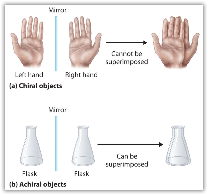
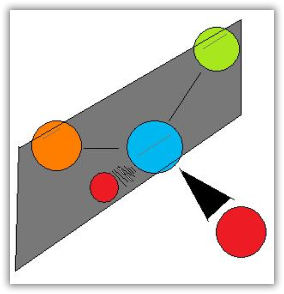
Optical isomers are molecules whose structures are mirror images but cannot be superimposed on one another in any orientation. Optical isomers have identical physical properties, although their chemical properties may differ in asymmetric environments. Molecules that are nonsuperimposable mirror images of each other are said to be chiral (pronounced “ky-ral,” from the Greek cheir, meaning “hand”). Examples of some familiar chiral objects are your hands, feet, and ears. As shown in Figure 11, your left and right hands are nonsuperimposable mirror images. (Try putting your right shoe on your left foot—it just doesn’t work.) An achiral object is one that can be superimposed on its mirror image, as shown by the superimposed flasks in Figure 11.
Most chiral organic molecules have at least one carbon atom that is bonded to four different groups, as occurs in the bromochlorofluoromethane molecule shown in part (a) in Figure 12. This carbon, designated by an asterisk in structural drawings, is called a chiral center or asymmetric carbon atom. Note that even if one were to flip over the left molecule over to the right, the atomic spatial arrangement will not be equal. This is equivalent to the left hand-right hand relationship, and is aptly referred to as ‘handedness’ in molecules. If the bromine atom is replaced by another chlorine (Figure 12b), the molecule and its mirror image can now be superimposed by simple rotation. Thus the carbon is no longer a chiral center. Asymmetric carbon atoms are found in many naturally occurring molecules, such as lactic acid, which is present in milk and muscles, and nicotine, a component of tobacco. A molecule and its nonsuperimposable mirror image are called enantiomers (from the Greek enantiou, meaning “opposite”).
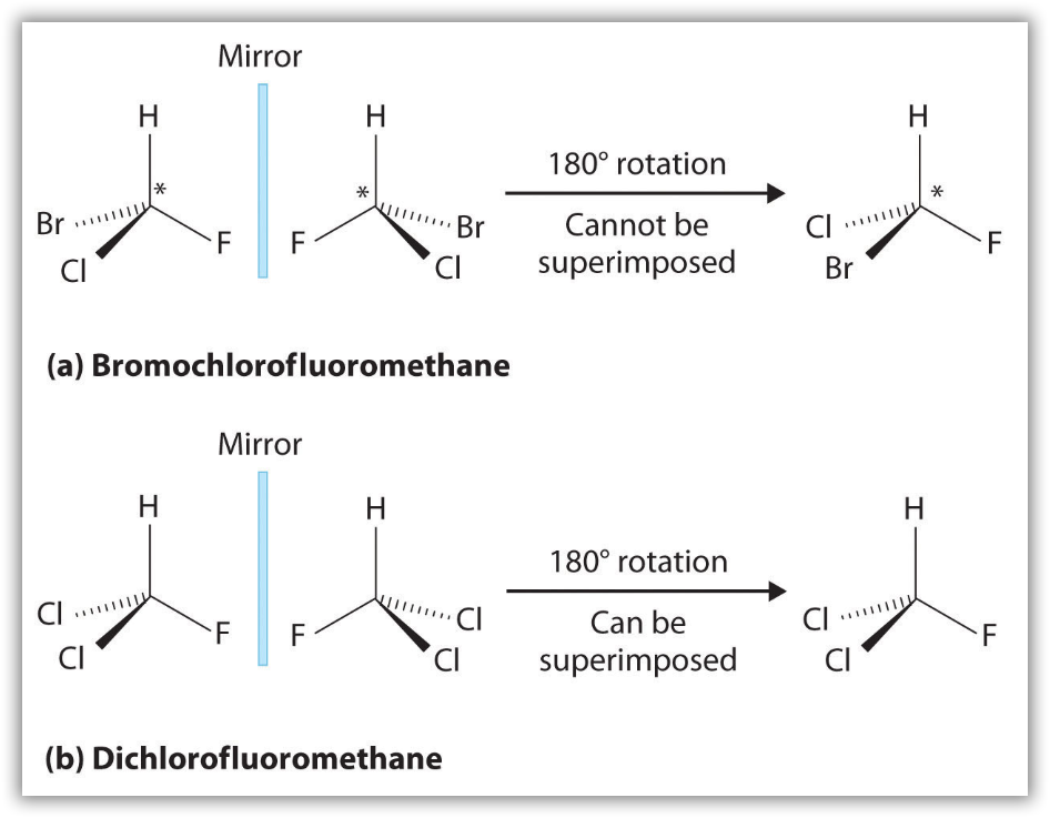
Notice the distinct characteristic of the achiral molecule in Figure 12b: it possesses two atoms of same element. If one were to create a plane that runs through the other two atoms, they will be able to create what is known as bisecting plane: the images on either side of the plan is the same as the other.
In other words, to distinguish chiral molecule from an achiral molecule, one must search for the existence of the bisecting plane in a molecule. All chiral molecules are deprive of bisecting plane, whether simple or complex. Looking for planes of symmetry in a molecule is useful, but often difficult in practice. In most cases, the easiest way to decide whether a molecule is chiral or achiral is to look for one or more stereocenters – with a few exceptions, the general rule is that molecules with at least one stereocenter are chiral, and molecules with no stereocenters are achiral. Carbon stereocenters are also referred to quite frequently as chiral carbons.
When evaluating a molecule for chirality, it is important to recognize that just because you see dashed and solid wedges in a structure, do not automatically assume that you are looking at a stereocenter.
In the 1960’s, a drug called thalidomide was widely prescribed in Western Europe to alleviate morning sickness in pregnant women.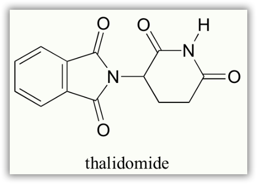
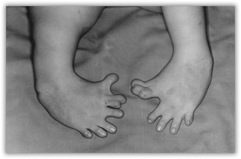
Thalidomide had previously been used in other countries as an antidepressant, and was believed to be safe and effective for both purposes. The drug was not approved for use in the U.S.A. It was not long, however, before doctors realized that something had gone horribly wrong: many babies born to women who had taken thalidomide during pregnancy suffered from severe birth defects.
Researchers later realized the that problem lay in the fact that thalidomide was being provided as a mixture of two different isomeric forms.
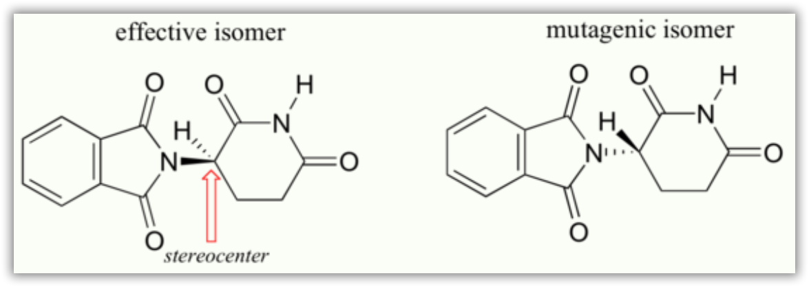
One of the isomers is an effective medication, the other caused the side effects. These two forms of thalidomide are enantiomers.
Ch6.4 Valence Bond Theory
Valence bond theory describes a covalent bond as the overlap of half-filled atomic orbitals (each containing a single electron) that yield a pair of electrons shared between the two bonded atoms. We say that orbitals on two different atoms overlap when a portion of one orbital and a portion of a second orbital occupy the same region of space. According to valence bond theory, a covalent bond results when two conditions are met: (1) an orbital on one atom overlaps an orbital on a second atom and (2) the single electrons in each orbital combine to form an electron pair. The mutual attraction between this negatively charged electron pair and the two atoms’ positively charged nuclei serves to physically link the two atoms through a force we define as a covalent bond. The strength of a covalent bond depends on the extent of overlap of the orbitals involved. Orbitals that overlap extensively form bonds that are stronger than those that have less overlap.
In addition to the distance between two orbitals, the orientation of orbitals also affects their overlap (other than for two s orbitals, which are spherically symmetric). Greater overlap is possible when orbitals are oriented such that they overlap on a direct line between the two nuclei. Figure 13 illustrates this for two p orbitals from different atoms; the overlap is greater when the orbitals overlap end to end rather than at an angle.
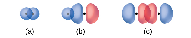
The overlap of two s orbitals (as in H2), the overlap of an s orbital and a p orbital (as in HCl), and the end-to-end overlap of two p orbitals (as in Cl2) all produce sigma bonds (σ bonds), as illustrated in Figure 14. A σ bond is a covalent bond in which the electron density is concentrated in the region along the internuclear axis; that is, a line between the nuclei would pass through the center of the overlap region. Single bonds in Lewis structures are described as σ bonds in valence bond theory.
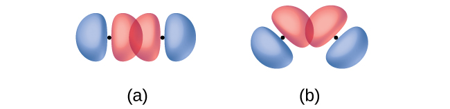
A pi bond (π bond) is a type of covalent bond that results from the side-by-side overlap of two p orbitals, as illustrated in Figure 15. In a π bond, the regions of orbital overlap lie on opposite sides of the internuclear axis. Along the axis itself, there is a node—a plane with no probability of finding an electron.

The wave function, ψ, contains information about each orbital and the wavelike properties of electrons in an isolated atom. When atoms are bound together in a molecule, the wave functions combine to produce new mathematical descriptions that have different shapes. This process of combining the atomic orbital wave functions is called hybridization and the new orbitals that result are called hybrid orbitals. The following ideas are important in understanding hybridization:
-
- Hybrid orbitals do not exist in isolated atoms. They are formed only in covalently bonded atoms.
- Hybrid orbitals have shapes and orientations that are differ from those of the atomic orbitals in isolated atoms.
- A set of hybrid orbitals is generated by combining atomic orbitals. The number of hybrid orbitals in a set is equal to the number of atomic orbitals that were combined to produce the set.
- All orbitals in a set of hybrid orbitals are equivalent in shape and energy.
- The type of hybrid orbitals formed in a bonded atom correlates with the local geometry of that atom.
- Hybrid orbitals overlap to form σ bonds. Unhybridized orbitals overlap to form π bonds.
Ch6.5 Hybridization
sp Hybridization
The beryllium atom in a gaseous BeCl2 molecule forms two σ bonds and has no lone pairs of electrons. There are two valence electrons in Be, and two of the Be atom’s four valence orbitals will mix to yield two hybrid orbitals. This hybridization process involves mixing of the valence s orbital with one of the valence p orbitals to yield two equivalent sp hybrid orbitals that are oriented in a linear geometry (Figure 16). The set of sp orbitals appears similar in shape to the original p orbital, but there is an important difference: one lobe is larger than the other, and the larger lobe will provide better overlap when forming a σ bond. The two electrons that were originally in the s orbital are now distributed to the two half filled sp orbitals, which will overlap with orbitals from the chlorine atoms to form two identical σ bonds.
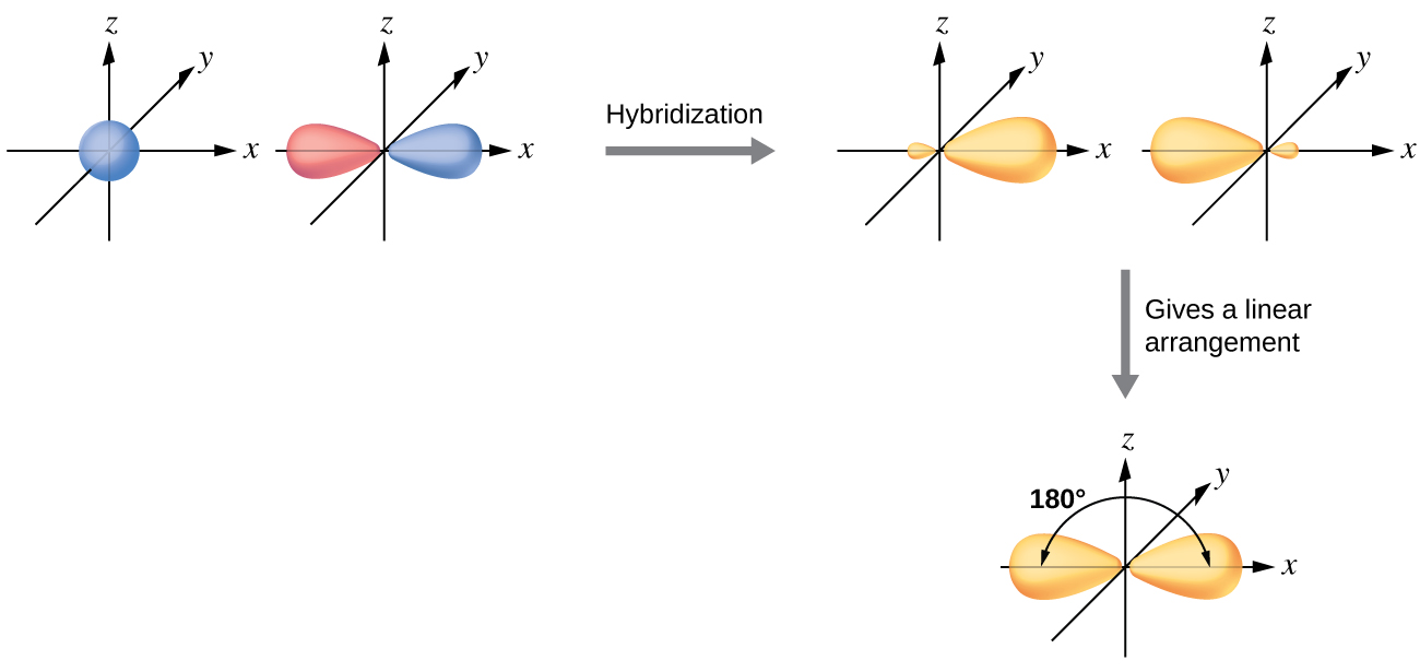
Figure 17 illustrates the electronic differences in an isolated Be atom vs a bonded Be atom in an orbital energy-level diagram. The sp orbital is higher in energy than the atomic 2s orbital and lower in energy than the atomic 2p orbital. We can see that the hybridized orbitals would not be energetically favorable for an isolated Be atom—the atomic orbitals are optimal. Hence, hybridized orbitals only form in covalently bonded atoms.
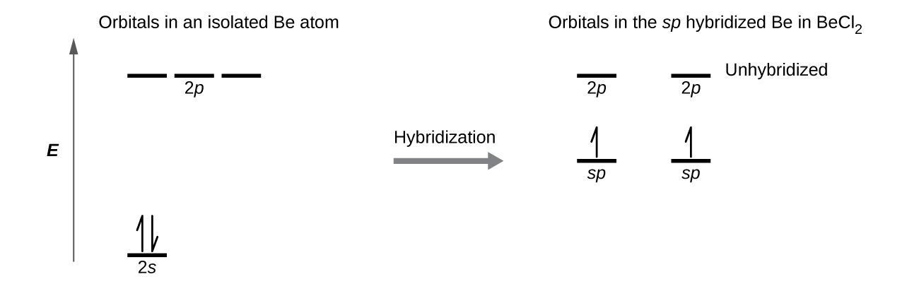
Each of the unpaired electron in an sp orbital will pair up with an unpaire electron in a Cl to form a Be-Cl σ bond. The 180º orientation of the two sp orbitals yields a linear geometry for BeCl2, same as what is predicted using VSEPR.
Check out the University of Wisconsin-Oshkosh website to learn about visualizing hybrid orbitals in three dimensions.
sp2 Hybridization
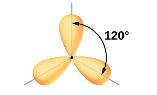
The mixing of one s orbital and two p orbitals produces three identical sp2 hybridized orbitals, which are oriented in a trigonal planar geometry (Figure 18).
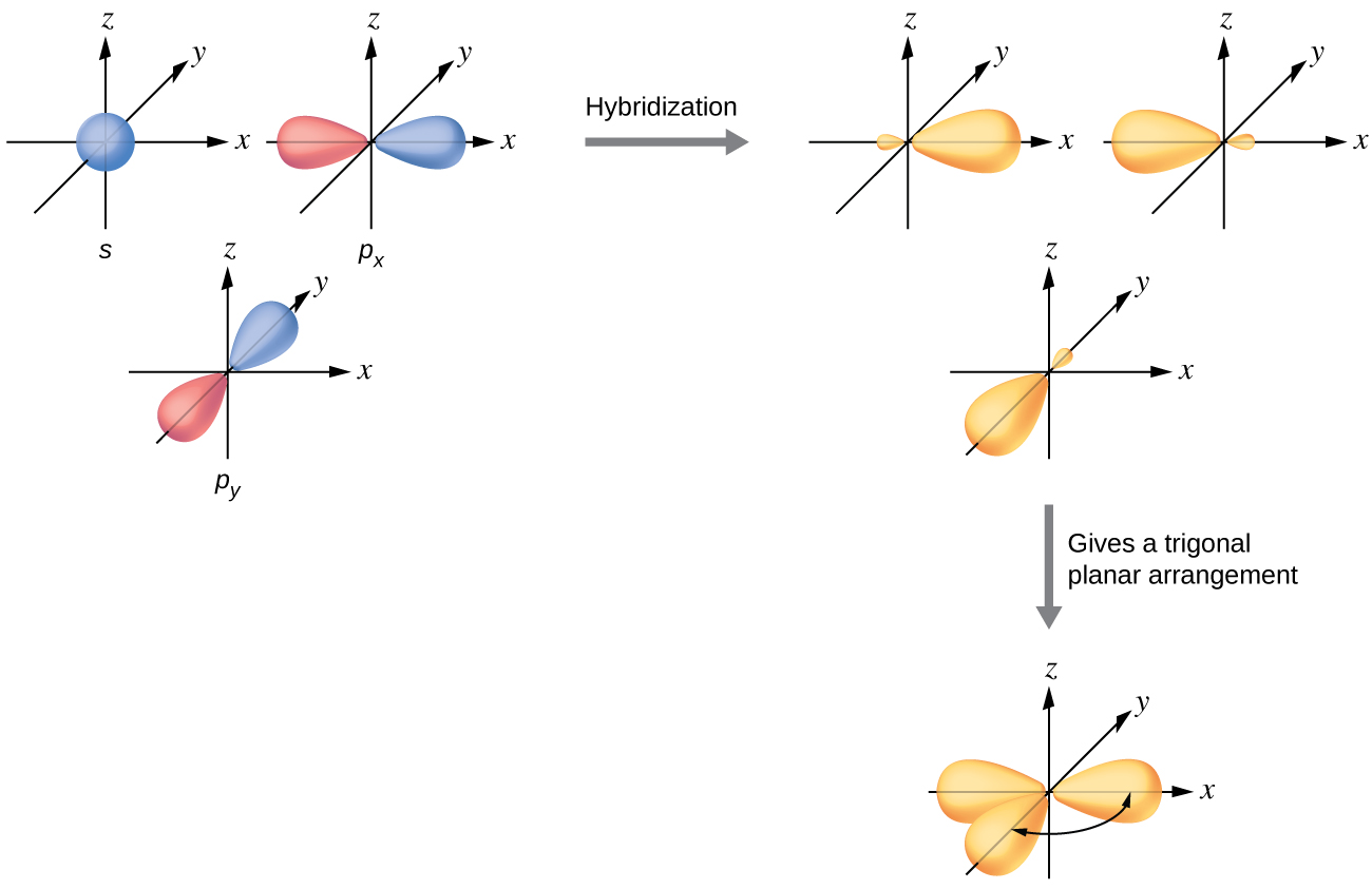
Sometimes for clarity these orbitals are drawn without the minor lobes, as in Figure 19.
In the borane molecule, BH3, the boron atom is involved in three σ bonds to hydrogen atoms (Figure 20). There are three valence electrons in boron, and the hybridization of one 2s orbital and two 2p orbital yields three sp2 hybrid orbitals. The comparison of these orbitals are shown in the orbital energy level diagram in Figure 21. The three valence electrons of the boron atom (two paired, one unpaired) are redistributed to the three sp2 hybrid orbitals, all half filled.
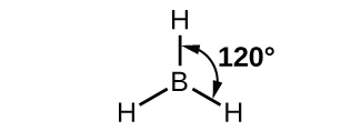
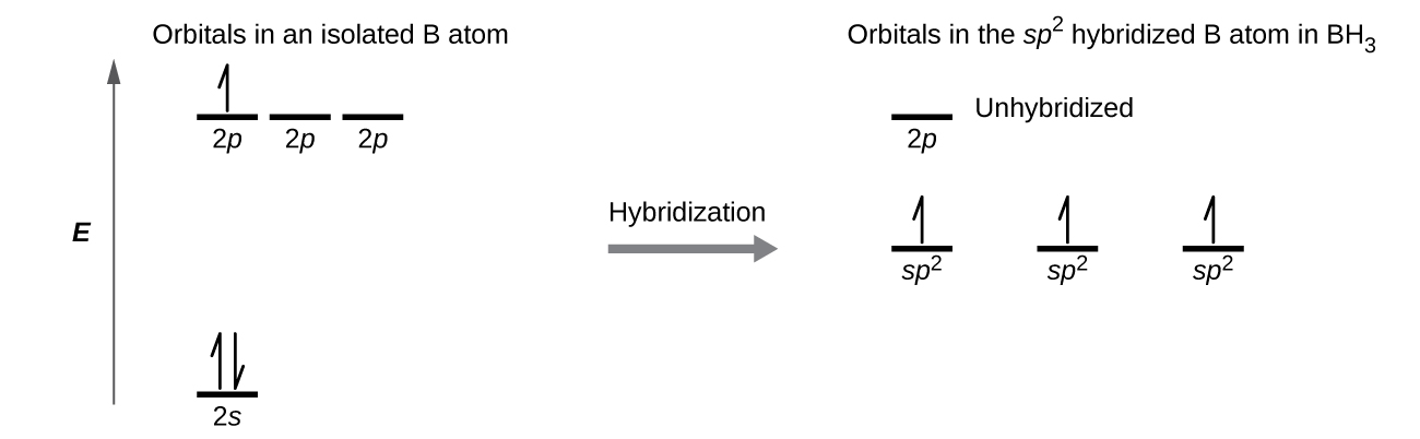
Each of the unpaired electron in an sp2 orbital will pair up with the unpaire electron in a hydrogen atom to form a B-H σ bond. The in-plane 120º orientation of the three sp2 orbitals yields a trigonal planar geometry for BH3.
sp3 Hybridization
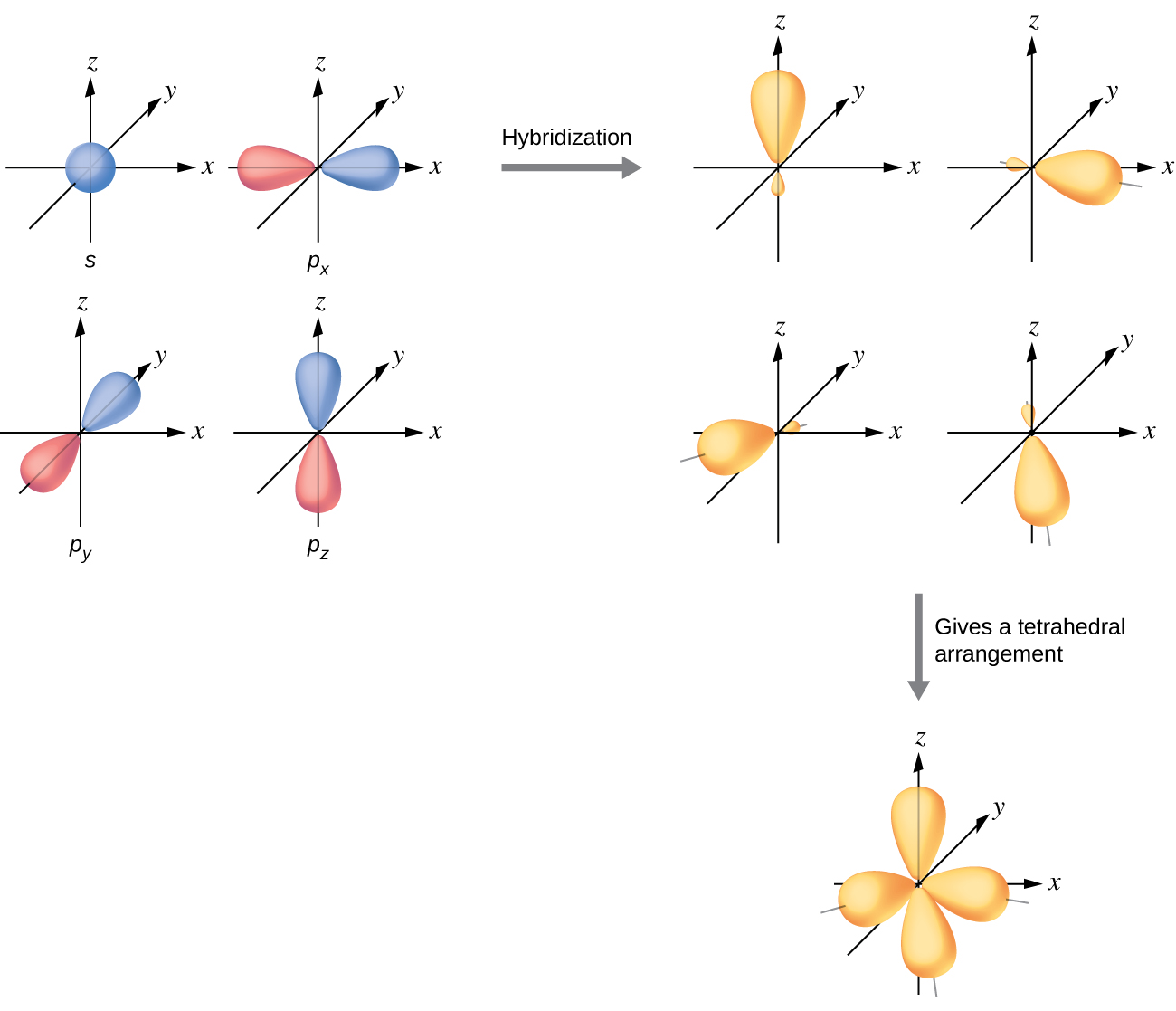
The mixing of one s orbital and all three p orbitals produces four identical sp3 hybridized orbitals, which are oriented in a tetrahedral geometry (Figure 22). Each of these hybrid orbitals points toward a different corner of a tetrahedron.
The carbon atom in methane, CH4, exhibits sp3 hybridization. The orbitals and electron distribution in an isolated C atom and in the bonded C atom in CH4 is illustrated in Figure 23.
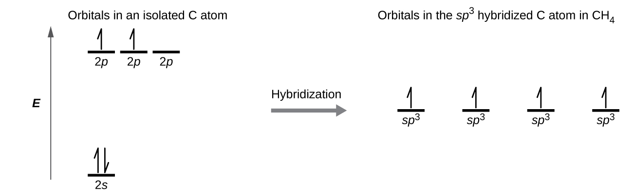
In the methane molecule, the 1s orbital of a hydrogen atom overlaps with one of the four sp3 orbitals of the carbon atom to form a C-H σ bond. This results in the formation of four strong, equivalent covalent bonds between the carbon atom and each of the hydrogen atoms to produce the tetrahedral CH4 molecule.
Lone Pairs
A hybrid orbital can also hold a lone pair of electrons. For example, the nitrogen atom in ammonia is surrounded by three bonding pairs and a lone pair of electrons directed to the four corners of a tetrahedron. The nitrogen atom is sp3 hybridized with one hybrid orbital occupied by the lone pair.
Ch6.6 Double and Triple Bonds
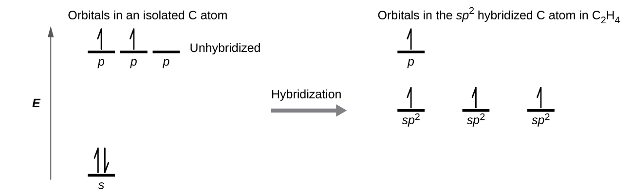
The Lewis structure of ethene, C2H4, shows us that each carbon atom is surrounded by one other carbon atom and two hydrogen atoms.
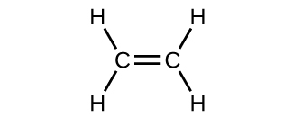
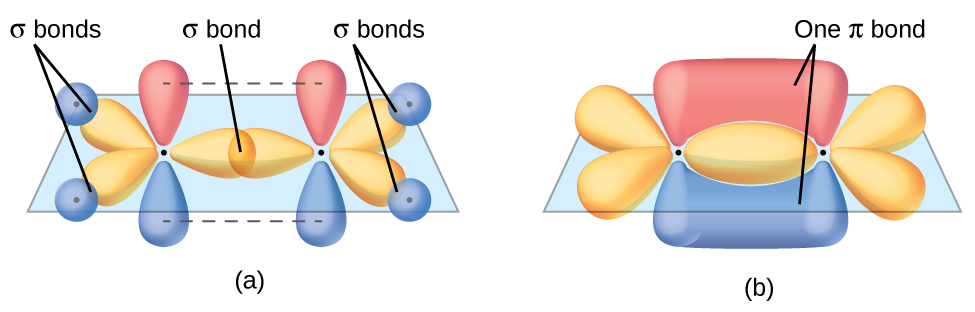
Each carbon atom has a trigonal planar geometry, and hence is sp2 hybridized. The sp2 orbitals result from hybridization of two of the 2p orbitals and the 2s orbital (Figure 24). These orbitals form the C–H σ bonds and the σ bond in the C=C double bond (Figure 25). The π bond in the C=C double bond results from the overlap of the unhybridized 2p orbital on each carbon atom. The 2p orbital (lobes shown in red and blue in Figure 25) is perpendicular to the plane of the sp2 hybrid orbitals. Thus when they overlap in a side-by-side fashion to form a π bond, the electron densities in the π bond are above and below the plane of the σ system.
In an ethene molecule, all the atoms are in the same plane. If the two planes of sp2 hybrid orbitals (from the two carbon atoms) are tilted relative to each other, the 2p orbital from each carbon would no longer be able to overlap efficiently to create the π bond. The planar configuration for the ethene molecule occurs because it is the most stable bonding arrangement. This is a significant difference between σ and π bonds: rotation around a σ bond occurs easily because the end-to-end orbital overlap does not depend on the relative orientation of the orbitals on each atom in the bond. In other words, rotation around the internuclear axis does not change the extent to which the σ bonding orbitals overlap because the bonding electron density is symmetric about the axis. In contrast, rotation about the internuclear axis would essentially break the π bond.
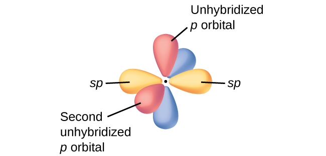
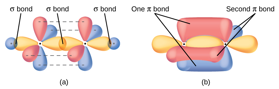
In molecules with sp hybrid orbitals, two unhybridized p orbitals remain on the atom (Figure 26). We find this situation in acetylene, H−C≡C−H. The sp hybrid orbitals of the two carbon atoms overlap end to end to form a σ bond between the carbon atoms (Figure 27). The remaining sp orbitals form σ bonds with hydrogen atoms. Each unhybridized 2p orbital on one carbon overlap side by side with an unhybridized 2p orbital on the other carbon, and in total form two π bonds. Because the two 2p orbitals in a single carbon atom are perpendicular to each other, the resulting π bonds are also perpendicular to each other. The two carbon atoms of acetylene are thus bound together by one σ bond and two π bonds, giving a triple bond.
Many molecules have more than one major resonance forms. In these resonance forms, various arrangements of π bonds are possible. Since the arrangement of π bonds involves the unhybridized orbitals, resonance does not influence the assignment of hybridization.
Example 8
Assignment of Hybridization Involving Resonance
Some acid rain results from the reaction of sulfur dioxide with atmospheric water vapor, followed by the formation of sulfuric acid. Sulfur dioxide, SO2, is a major component of volcanic gases as well as a product of the combustion of sulfur-containing coal. What is the hybridization of the S atom in SO2?
Solution
The resonance structures of SO2 are

In either resonance structure, the sulfur atom has one single bond, one double bond, and one lone pair of electrons. Therefore, the electron-region geometry is trigonal planar, and the hybridization of the sulfur atom is sp2. The lone pair resides in one of the sp2 orbitals, and the unhybridized p orbital is involved in the delocalized π bonding.
Check Your Learning
Another acid in acid rain is nitric acid, HNO3, which is produced by the reaction of nitrogen dioxide, NO2, with atmospheric water vapor. What is the hybridization of the nitrogen atom in NO2? (Note: the lone electron on nitrogen occupies a hybridized orbital just as a lone pair would.)
Answer:
sp2
