
Unit One
Day 6: Covalent Bonding
As you work through this section, if you find that you need a bit more background material to help you understand the topics at hand, you can consult “Chemistry: The Molecular Science” (5th ed. Moore and Stanitski) Chapter 6-1 and 6-12, and/or Chapter 4.1-4.4 in the Additional Reading Materials section.
D 6.1 Covalent Bond Formation
A large fraction of the more than 140 million chemical substances currently known are covalent molecular compounds. Each covalent molecular compound is made up of molecules. Each molecule is a collection of atoms connected by covalent bonds. Within a molecule the atoms and bonds have specific orientations: for example, all water molecules have two hydrogen atoms covalently bonded to one oxygen atom with an angle of 104.5o between the bonds. In general, covalent bonds hold atoms together and have specific orientations in space.
Activity 1
If you wrote that a covalent chemical bond involves sharing electrons between atoms, that’s a good start. But how does sharing electrons hold atoms together?
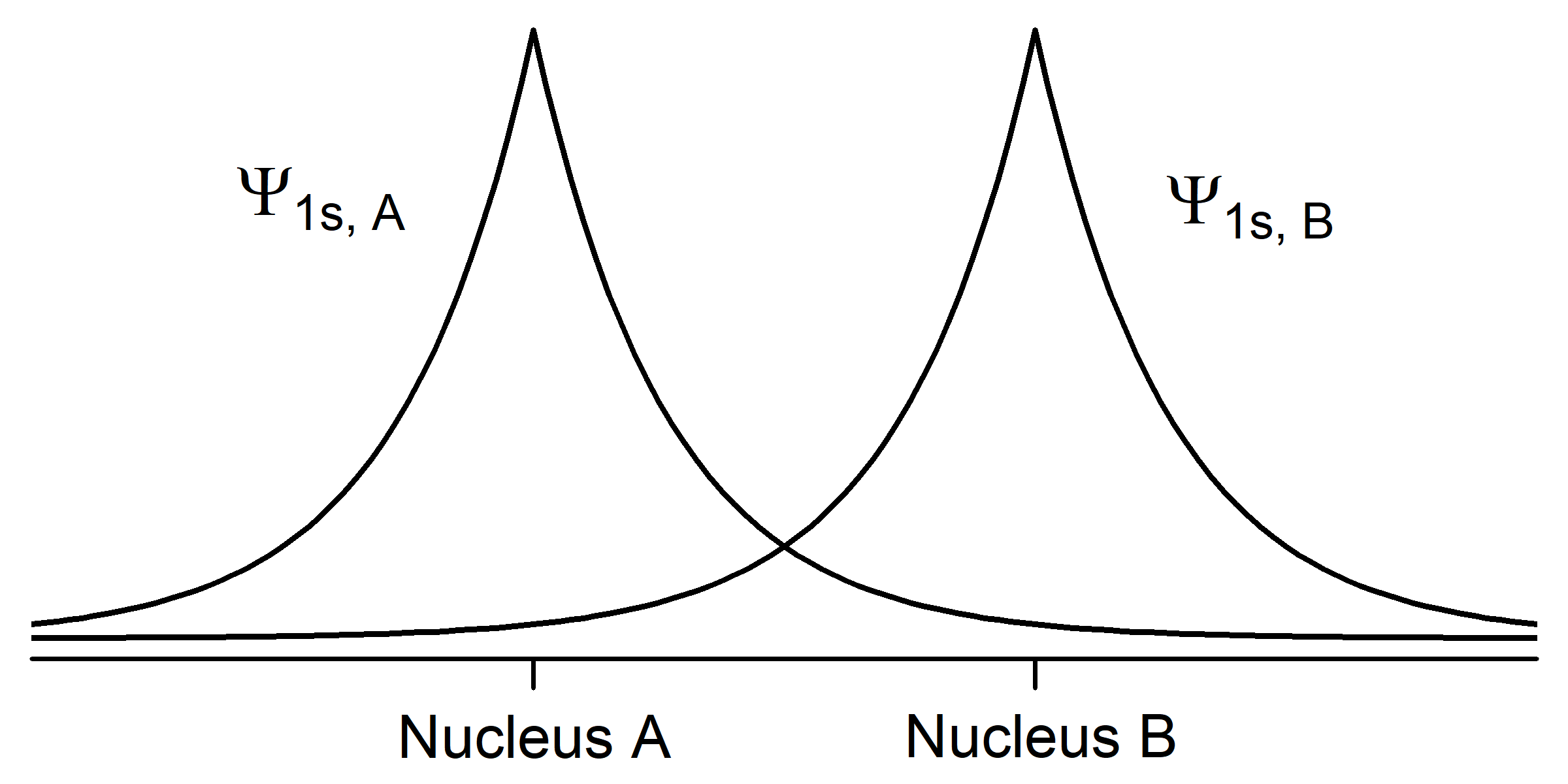
To understand this better, let’s apply the ideas of quantum mechanics to two hydrogen atoms. Each hydrogen atom in its ground state has a single 1s electron whose electron-density distribution is shown in Activity 2, Figure 1. (H atom wave functions and electron-density distributions were discussed in Day 3, Section D3.3.) The density of dots in the figure is proportional to the square of a wave function Ψ1s that has maximum amplitude at the nucleus and decreases exponentially with increasing distance from the nucleus.
Activity 2
In your notebook, describe how the two figures are related. How does the number of dots per unit area correlate with the graph of amplitude of the wave function Ψ1s? Why is the wave function amplitude greatest at the nucleus? Why is the wave function amplitude symmetric from one side of the nucleus to the other?
From here on we will use wave-function graphs, but you should keep in mind how they are related to electron density.
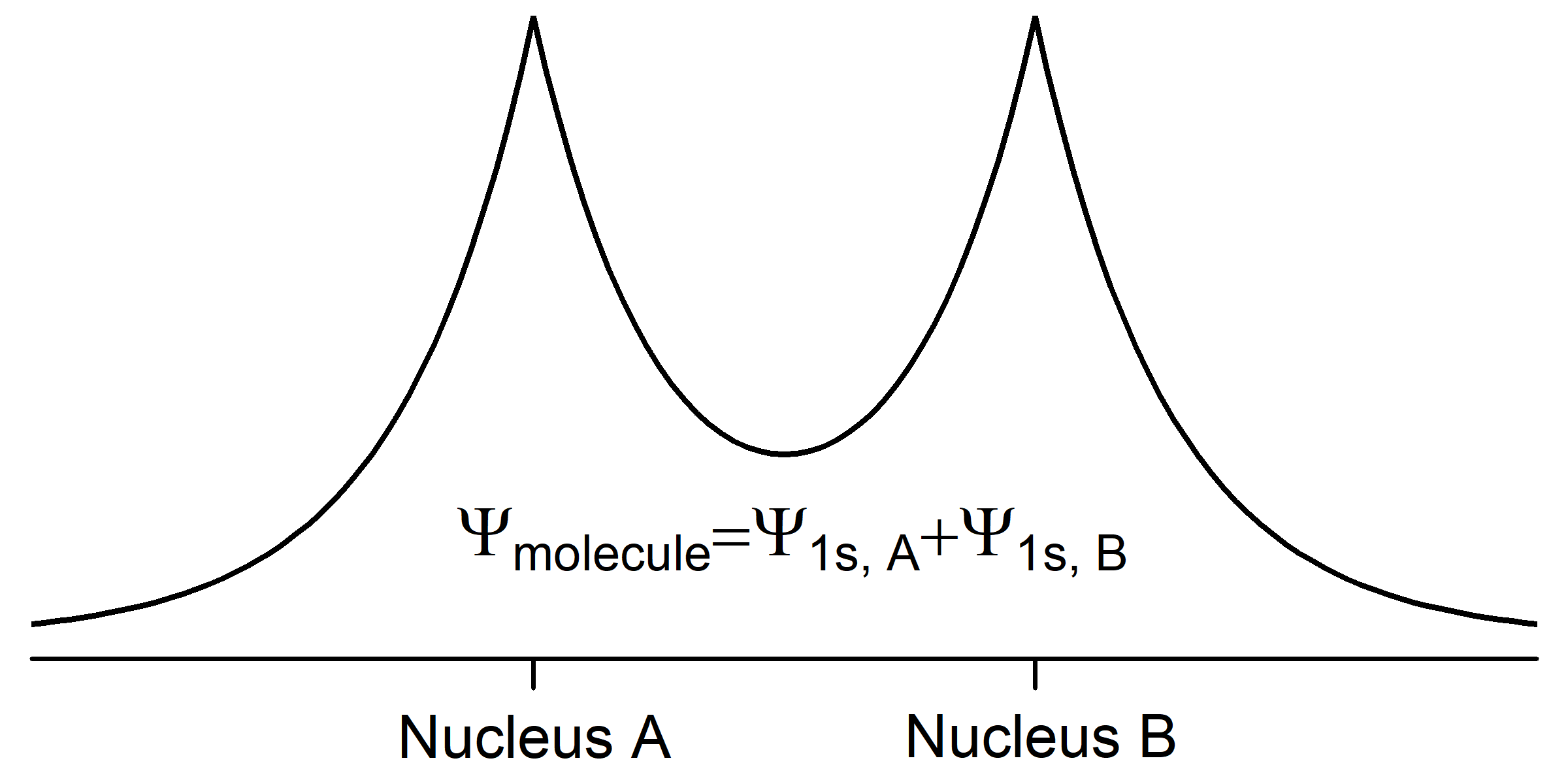
When two hydrogen atoms approach each other, their wave functions begin to overlap (occupy the same space) and the amplitude of the total wave function for the two atoms (a hydrogen molecule) is the sum of the amplitudes of the two individual wave functions. We can describe the molecular wave function as a superposition of the two atomic wave functions,
Ψmolecule = Ψ1sA + Ψ1sB,
where A and B designate the two nuclei. This superposition of waves results in chemical bonding by lowering the total energy of the pair of atoms. Because its energy is lower, the molecule is more stable than the separated atoms.
The total energy of a hydrogen molecule, H2, is the sum of the potential energy and the kinetic energy.
Etotal = Epotential + Ekinetic.
The potential energy of each electron becomes more negative in the molecule because the electron is close to and attracted by two nuclei, not just one. Notice that in Fig. 3 the amplitude of Ψmolecule is larger between the nuclei than for either atomic wave function by itself; this increased electron density attracts both nuclei, lowering the potential energy. The kinetic energy of each electron becomes less positive because each electron is spread over both nuclei (we say that each electron is delocalized over the molecule). According to the de Broglie relation, [latex]\lambda = \dfrac{h}{mv}[/latex], an electron’s wavelength is inversely proportional to its velocity. The kinetic energy of an electron is proportional to its velocity squared (Ekinetic = ½mv2). So spreading out the electron wave over both nuclei increases its wavelength and decreases its kinetic energy.
Think about what happens as two hydrogen atoms approach each other as depicted in Figure 4. At a large distance, such as 300 pm, the two atomic wave functions begin to overlap, the electrons are delocalized over two nuclei, and their kinetic energy is small (and positive). There is only a little overlap of the atomic wave functions, so the potential energy (which is negative) is also small. As seen in Figure 4. the total energy is only a little less than the energy of two completely separated H atoms. As the atoms get closer, the energy decreases because the potential energy becomes more and more negative until a minimum total energy is reached at a separation of 74 pm. At shorter distances the total energy increases for two reasons: potential energy decreases more slowly because the positive nuclei repel each other and, because the molecule is getting quite small, electron delocalization is less and the kinetic energy increases rapidly.
D6.2 Constructive and Destructive Interference
The case we have just described is equivalent to constructive interference of the electron waves for the two hydrogen atoms. It occurs when the two waves are in-phase—when the two waves are both vibrating up (or down) at the same time. A second possibility is that the two waves are out-of-phase—one is moving up when the other is moving down. This results in destructive interference between the waves. Examples of constructive and destructive interference are shown in the two videos below. Note that in the destructive interference video there is a point in the middle of the wave device that never moves up or down. This point has zero amplitude all the time and is a node.
Exercise 1: Molecular Orbital Formation
Based on the mathematical equation for the molecular orbital involving constructive interference, write an equation for a molecular orbital involving destructive interference. Also, make a diagram showing the two atomic wave functions (similar to Fig. 2) and the superposition of the wave functions (similar to Fig. 3) for the destructive interference case. (As you study chemistry, it is a good idea to pause regularly to think about the implications of what you are learning; this example asks a question like the ones you should regularly ask yourself.)
Either way you write the wave function for Exercise 1, the minus sign causes one wave to be out of phase with the other—the positive amplitude of one wave is partially (or sometimes wholly) cancelled by the negative amplitude of the other. About halfway between the nuclei, when both wave functions have the same amplitude, the cancellation is complete. Ψ*molecule always has zero amplitude in between the nuclei; that is, there is a node in this molecular orbital. As was true of atomic wave functions, more nodes correspond to higher energy. So the destructive interference case results in higher energy. This makes sense because the node reduces electron density between the nuclei, compared with the individual atoms’ electron densities. Reduced electron density means less attraction than if the atomic orbitals did not interact at all.
The molecular wave functions are analogous to the atomic wave functions (orbitals). The molecular wave functions are called molecular orbitals (MOs). The diagram in Figure 5 shows relative energies and electron densities of each H atom and of the H2 molecule for constructive (lower E) and destructive (higher E) interference. The lower-energy orbital is called a bonding MO because an electron in this orbital is lower in energy than in an individual atom and therefore contributes to bonding. The higher-energy orbital is called an antibonding MO because an electron in this orbital would be more stable in individual separate atoms and thus makes a negative contribution to bonding.
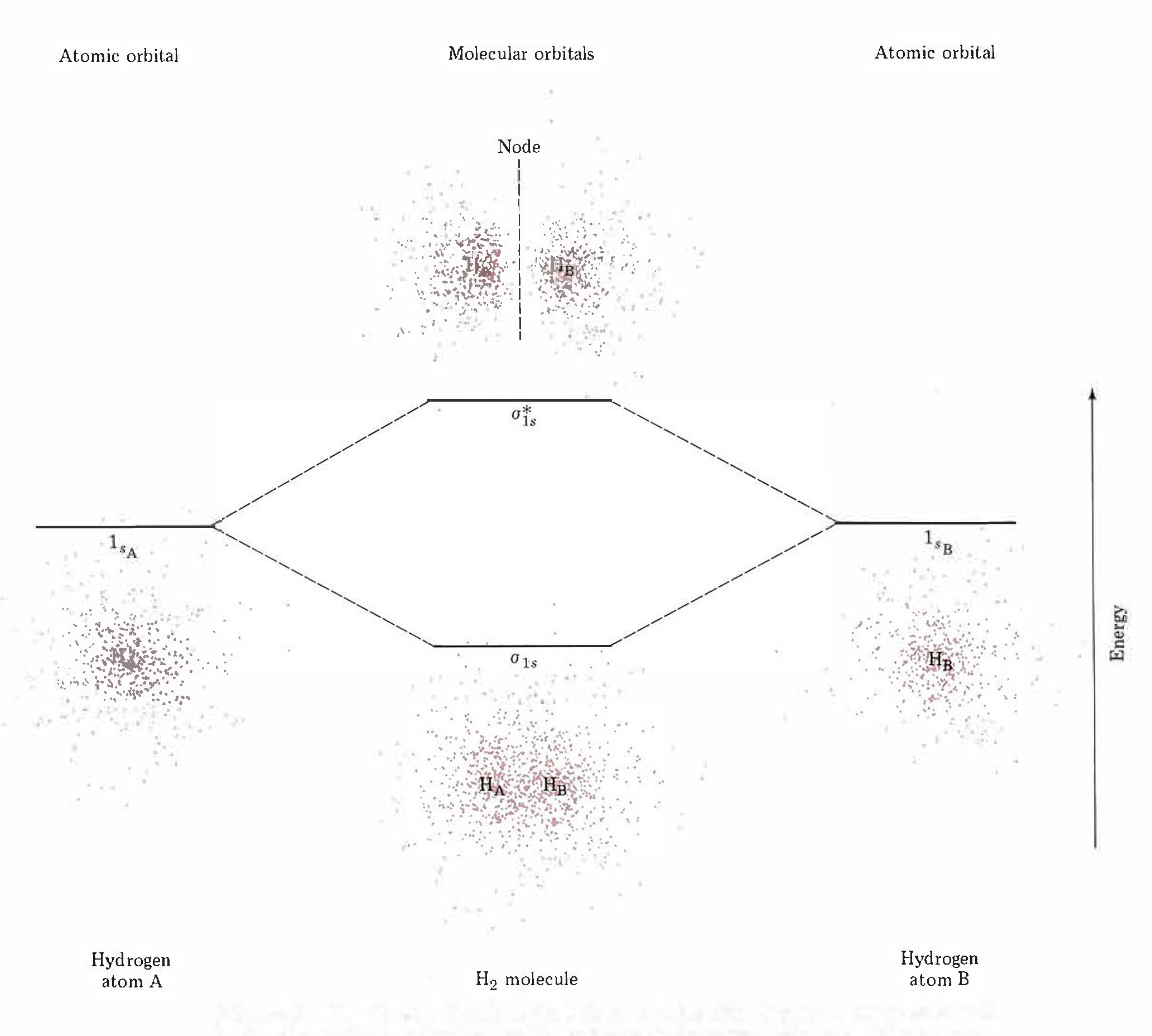
Note that the labels for the molecular orbitals are σ1s and σ*1s. The subscript “1s” designates that the MOs are derived from the 1s atomic orbitals (AOs). The “*” indicates an antibonding MO. But what does the Greek sigma mean? It turns out that σ denotes the symmetry of the MO with respect to the internuclear axis (the line connecting the two nuclei). A MO that is cylindrically symmetric is designated σ. Cylindrically symmetric means that if you stood the molecule on end and spun it around the internuclear axis it would look the same all the time. The shapes of MOs relative to the internuclear axis are designated by Greek letters σ, π, δ that are analogous to the Roman letters s, p, d that designate shapes of atomic orbitals.
One more thing about orbitals is that chemists use a shorthand to show both the shape and phase of AOs and MOs. It is much easier to make a two-dimensional drawing, so the sphere of a 1s AO is drawn as a circle and the mathematical sign of the wave function (the phase) is indicated by color or by a plus or minus sign. For example, formation of the σ1s MO from two 1s AOs is shown like this
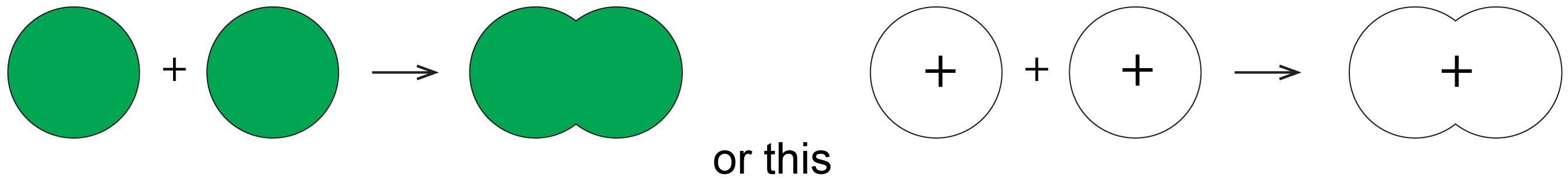
where the green circles represent boundary surfaces of H atom electron distributions, each with positive phase (like the ones in Fig. 5), and the green oval represents the H2 molecule electron distribution, also with positive phase (like the lower-energy electron density diagram in Fig. 5). (When necessary, we will use yellow to designate negative phase.) Alternatively, a + sign is used to designate positive phase and a − sign to designate negative phase.
Exercise 2: Molecular Orbital Formation
D6.3 Molecular Orbital Electron Configurations and Bond Order
Just as an atom has an electron configuration, so does a molecule. The electron configuration can be obtained by counting the total number of electrons and filling electrons into a MO energy-level diagram such as Figure 5, following the same rules as for atomic electron configurations:
- Each MO can hold at most two electrons; the two electrons must have opposite spin.
- Arrange the MOs in order of increasing energy.
- Add electrons to the lowest-energy MO first and then to successively higher-energy MOs.
- If two or more MOs have the same energy, apply Hund’s rule: put one electron into each orbital before pairing any electrons.
For the H2 molecule there is one electron from each H atom, so there are two electrons to fill into the MOs. Two electrons with opposite spin can fill the lower-energy MO so the electron configuration is (σ1s)2.
Exercise 3: Molecular Orbitals and Electromagnetic Radiation
Suppose that a photon collides with a hydrogen molecule. Based on what you have learned so far in this section, propose at least two hypotheses about what might happen. Write each hypothesis in your notebook. Then compare with the result below.
Additional Practice
Consider a situation in which a hydrogen molecule might emit a photon. Describe how you can use the wavelength of the emitted photon to learn something about the energy levels of the H2 molecule.
The two electrons in the σ1s bonding MO form the covalent bond between the two H atoms. In general, a covalent bond involves superposition of two or more atomic orbitals, where electron density close to atomic nuclei is increased and electron potential energy is decreased. Electrons are shared between pairs of nuclei or more widely among several nuclei within a molecule. The configuration (σ1s)2 indicates a single bond between two H atoms.
In some cases more than two electrons can be shared between two nuclei. This gives rise to the idea of bond order, the number of shared electron pairs between two atoms. Based on an MO energy-level diagram, bond order can be defined as:
where nbonding e¯ is the number of electrons in bonding MOs and nantibonding e¯ is the number of electrons in antibonding MOs.
Exercise 4: Bond Order
Under special conditions it is possible to ionize an electron from a hydrogen molecule to produce the molecule-ion (polyatomic ion) H2+. Under different conditions it is possible to add an electron to a hydrogen molecule to produce H2−. Which of these has a stronger bond?
Additional Practice
Calculate the bond order for the He2 molecule and predict whether such a molecule should exist.
D6.4 Molecular Orbitals for Second-Row Elements
F2, O2, and N2 are examples of diatomic molecules formed by elements from the second row of the periodic table. Molecular orbitals for these molecules are a bit more complicated than for H2 because bonding involves p atomic orbitals as well as s atomic orbitals.
Exercise 5: Shapes and Phases of p Atomic Orbitals
Draw a Cartesian coordinate system showing x, y, and z axes and draw a schematic diagram of a px atomic orbital. Show phases using either color or plus and minus signs. On a second coordinate system make a similar drawing of a pz atomic orbital.
Additional Practice
Suppose you spin the atom around the z axis. Classify the px and pz orbitals with respect to cylindrical symmetry around the z axis. Which orbital has a node that contains the z axis?
Now think about what happens when two atoms containing p orbitals approach each other. Assume that the internuclear axis is the z axis. This means that the two pz AOs are aligned along the internuclear axis while the px and py AOs on each atom are oriented perpendicular to the internuclear axis. The two pz AOs can form a bonding and an antibonding combination:
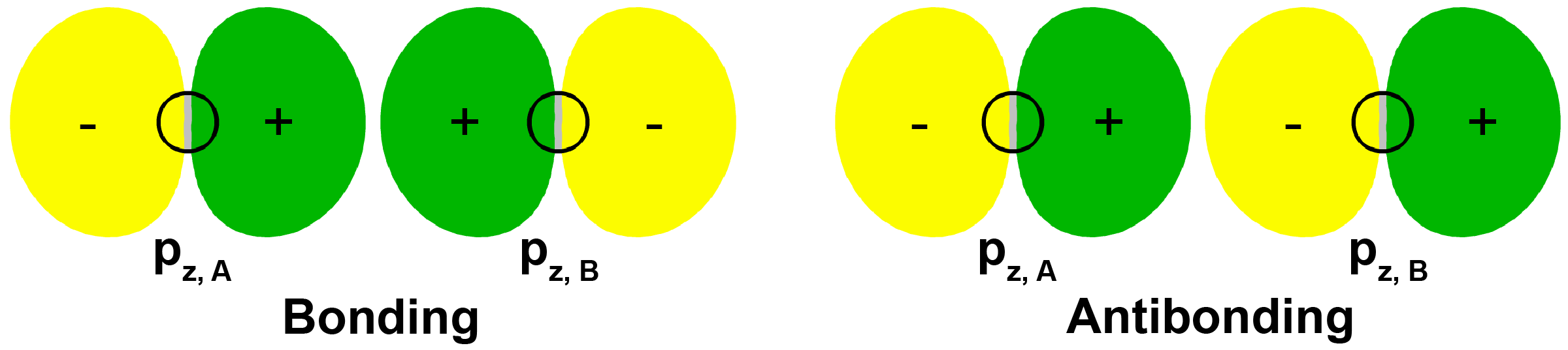
MOs derived from these two combinations are labeled [latex]\sigma_{\text{2}p_\text{z}}[/latex] and [latex]\sigma^*_{\text{2}p_\text{z}}[/latex]. Make sure you understand why these MOs are labeled sigma.
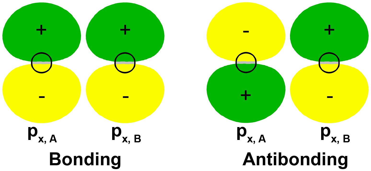
It is also possible to make bonding and antibonding combinations from the two 2px AOs and from the two 2py AOs. Here is a diagram for the two ways the 2px AOs can be combined. Notice that the orbitals overlap side-by-side, not end-on, because the 2px AOs are aligned perpendicular to the internuclear axis.
Exercise 6: Molecular Orbitals Involving p Atomic Orbitals
Assume that two atoms approach along the z axis. Draw two diagrams showing MOs formed from two pz AOs, one on each of the atoms. Label one diagram “Bonding MO, [latex]\sigma_{\text{2}p_\text{z}}[/latex]” and the other diagram “Antibonding MO, [latex]\sigma^*_{\text{2}p_\text{z}}[/latex]“. Explain why you labeled each MO as you did. (Note that these diagrams are derived from but not the same as the diagrams above.)
Additional Practice
Consider overlap of a py AO on each of the two approaching atoms. (Assume that the y axis on one atom is parallel to the y axis on the other atom.) Draw a MO that is a bonding combination of the two py AOs and a MO that is antibonding. Label them analogously to how you labeled the MOs in the first part of this example.
When two p orbitals overlap side-by-side, the bond formed is not symmetric with respect to rotation around the bond axis. Thus, the bond is not a sigma bond. If you look along the bond axis the bond looks similar to a p atomic orbital. Because it is a molecular orbital it is called a pi (π) orbital.

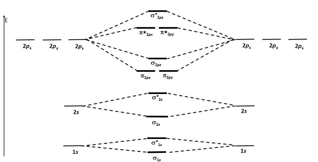
Think about all atomic orbitals that are occupied in Ne, the last element in the second period: 1s, 2s, 2pz, 2px, and 2py. For each atomic-orbital pair (such as 2s on atom A with 2s on atom B) overlap produces a bonding and an antibonding combination. There is sigma bonding and antibonding for 1s, 2s, and 2pz. There is pi bonding and antibonding for 2px, and 2py. These ideas result in the MO energy-level diagram shown here.
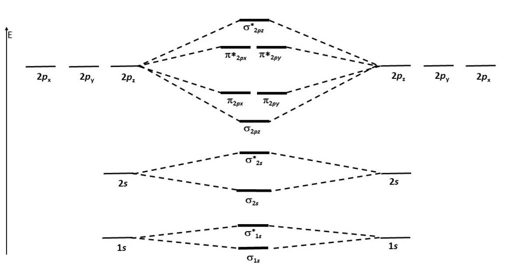
Notice in the diagram that there are two π bonding MOs that have the same energy, [latex]\pi_{\text{2}p_\text{x}}[/latex] and [latex]\pi_{\text{2}p_\text{y}}[/latex]. This happens because the side-by-side overlap of two 2px AOs is identical to the side-by-side overlap of two 2py AOs. The same overlap gives the same energy lowering for constructive interference. Similar reasoning leads to the conclusion that the [latex]\pi^*_{\text{2}p_\text{x}}[/latex] and [latex]\pi^*_{\text{2}p_\text{y}}[/latex] MOs also have the same energy. Recognizing that these MOs are degenerate is important when applying Hund’s rule to determine electron configurations.
Figure 7 shows the formation of the two perpendicular π bonds as two N atoms approach each other. (The two molecular diagrams in the figure are the same N2 molecule; one shows the px – px orbital overlap and the other shows the py – py orbital overlap.)
Exercise 7: Molecular Orbitals Electron Configurations
Additional Practice
Calculate the bond order for F2.
D6.5 MOs for Molecules with More Than Two Atoms
Molecules with three or more atoms can have molecular orbitals that span the entire molecule. The MOs are derived from AOs of all atoms in the molecule. Both the MO wave functions and the structure of the energy-level diagram are more complicated than for diatomic molecules, but mathematical techniques exist for deriving appropriate MO wave functions and displaying the electron densities that form chemical bonds. In this course we will not deal with these more complicated cases except to make several general points:
- The number of MOs for a molecule equals the number of AOs on the atoms that make up the molecule.
- The energies of the MOs increase as the number of nodes in the MO increases.
- MOs can extend over the entire molecular structure; they are not necessarily confined to pairs of atoms.
- It is possible to adjust MOs to display electron density localized between pairs of atoms or on individual atoms; this enables us to still use Lewis structures to represent electrons in chemical bonds as lines and electrons on a single atom as dots.
Exercise 8: MOs for Polyatomic Molecules
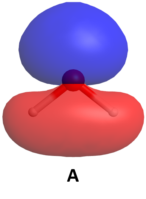
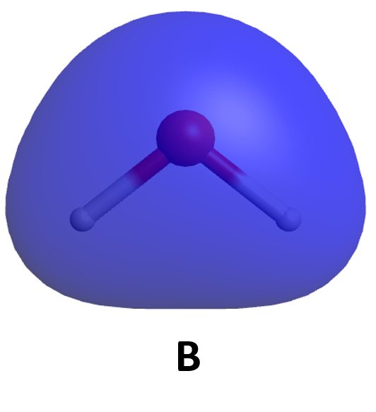
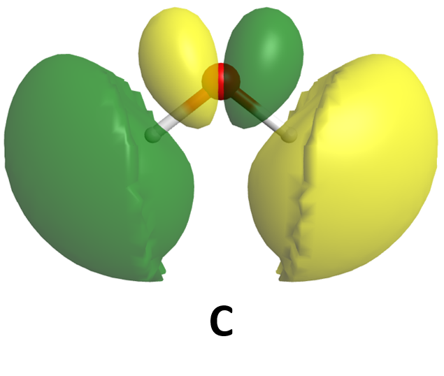
Some of the molecular orbitals for a water molecule are shown here. Based only on what you know about the appearance of bonding and antibonding orbitals, rank these MOs from lowest-energy to highest-energy. (Click on each image for a rotatable 3D view of the MO.)
Because the MOs for molecules consisting of three or more atoms are complicated and time-consuming to draw, we usually represent covalent bonds by bond lines and electrons not involved in bonds as dots. (That is, we represent molecules using Lewis structures.) Thus, the molecules N2 and H2O are drawn like this:
![]()
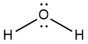
Lewis structures are the subject of the next section (Day 7) of this online resource.
Activity 3
Podia Question
The molecule C2 is unstable compared to molecules in which two carbon atoms are bonded to hydrogen atoms as well as to each other; however, C2 is stable enough in the gas phase to be studied experimentally. C2 is found to have no unpaired electrons.
- Use the MO energy-level diagram in Figure 6 to predict the electron configuration of C2. Does your result agree with the experimental observation that C2 has no unpaired electrons?
- Consider this MO energy-level diagram. Is this a better diagram than Figure 6 for C2? Explain. (Hint: work out the electron configuration for C2 with each diagram.)
- Without using Schrödinger’s equation to calculate accurate energy levels, it is difficult to predict the relative order of energy levels for second-row diatomic molecules. Based on the information in this question, predict whether the molecule B2 is paramagnetic. Explain how you arrived at your prediction.
Two days before the next whole-class session, this Podia question will become live on Podia, where you can submit your answer.
