
6 VSEPR and Polarity
Learning Objectives
- Identify the molecular geometry of a given atom and the bond angles in organic compounds.
| VSEPR Theory | Molecular Polarity | - Identify hybrid orbitals used in bonding and use hybridization of carbon atoms (sp3, sp2, and sp) to rationalize molecular structure.
| Valence Bond Theory | Hybridization | sp3 | sp2 | sp |
VSEPR Theory
Valence shell electron-pair repulsion theory (VSEPR theory) enables us to predict the molecular geometry, including approximate bond angles around a central atom, of a molecule from an examination of the number of bonds and lone electron pairs in its Lewis structure. The VSEPR model assumes that electron pairs in the valence shell of a central atom will adopt an arrangement that minimizes repulsions between these electron pairs by maximizing the distance between them. The electrons in the valence shell of a central atom form either bonding pairs or nonbonding lone pairs. The electrostatic repulsion of these electrons is reduced when they assume positions as far away from each other as possible.
As a simple example of VSEPR theory, let us predict the structure of a gaseous BeF2 molecule. The Lewis structure of BeF2 (Figure 1) shows only two electron pairs around the central beryllium atom. With two bonds and no lone pairs of electrons on the central atom, the bonds are as far apart as possible, and the electrostatic repulsion between these regions of high electron density is reduced to a minimum when they are on opposite sides of the central atom. The F-Be-F bond angle is 180° (Figure 1) in the BeF2 molecule resulting in a linear geometry.

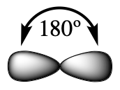
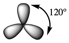
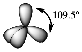
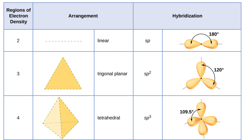
Table 1 illustrates electron region geometries that minimize the repulsions between regions of high electron density (bonds and/or lone pairs). Two regions of electron density around a central atom in a molecule form a linear geometry; three regions form a trigonal (or triangular) planar geometry; and four regions form a tetrahedral geometry.


Electron Region Geometry versus Molecular Geometry
It is important to note that electron region geometry around a central atom is not the same thing as its molecular geometry. The electron region geometries shown in Table 1 describe all regions where electrons are located. Bonds and lone pairs are treated equally. Molecular geometry describes the location of the atoms, not the lone pairs of electrons. The electron region geometries will be the same as the molecular geometries when there are no lone pairs of electrons around the central atom, but they will be different when there are lone pairs present on the central atom.
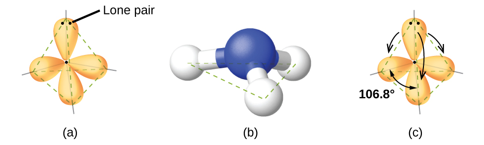
For example, the methane molecule, CH4, which is the major component of natural gas, has four bonding pairs of electrons around the central carbon atom; the electron region geometry is tetrahedral, as is the molecular geometry (Figure 2). On the other hand, the ammonia molecule, NH3, also has four electron pairs associated with the nitrogen atom, and thus has a tetrahedral electron region geometry. However, one of these regions is a lone pair and this lone pair influences the shape of the molecule, giving it a molecular geometry of trigonal pyramidal (Figure 3).

As seen in Figure 3, small distortions from the ideal angles in Table 1 can result from differences in repulsion between various regions of electron density. VSEPR theory predicts these distortions by establishing an order of repulsions and an order of the amount of space occupied by different kinds of electron pairs. This order of repulsions determines the amount of space occupied by different regions of electrons. A lone pair of electrons occupies a larger region of space than the electrons in a triple bond; in turn, electrons in a triple bond occupy more space than those in a double bond, and so on. The order of sizes from largest to smallest is:
Consider formaldehyde, H2CO, which is used as a preservative for biological and anatomical specimens (seen below). This molecule has regions of high electron density that consist of two single bonds and one double bond. The basic geometry is trigonal planar with 120° bond angles, but we see that the double bond causes slightly larger angles (121°), and the angle between the single bonds is slightly smaller (118°).

In the ammonia molecule, the three hydrogen atoms attached to the central nitrogen are not arranged in a flat, trigonal planar molecular geometry, but rather in a three-dimensional trigonal pyramid (Figure 3) with the nitrogen atom at the apex and the three hydrogen atoms forming the base. The ideal bond angles in a trigonal pyramidal structure are based on the tetrahedral electron pair geometry. Again, there are slight deviations from the ideal because lone pairs occupy larger regions of space than do bonding electrons. The H–N–H bond angles in NH3 are slightly smaller than the 109.5° angle in a regular tetrahedron (Table 1) because the lone pair of electrons occupy more space than a single bond (Figure 3). Table 2 illustrates the ideal molecular geometry predicted for a given combination of lone pairs and bonding pairs.
Predicting Electron Pair Geometry and Molecular Geometry
The following procedure uses VSEPR theory to determine the electron pair geometry and molecular geometry for a given molecule:
- Draw the Lewis Structure of the molecule or polyatomic ion.
- Count the number of regions of electron density (lone pairs and bonds) around the central atom. A single, double, or triple bond counts as one region of electron density.
- Identify the electron region geometry based on the number of regions of electron density: linear, trigonal planar, or tetrahedral (Table 2, first column).
- Use the number of lone pairs to determine the molecular geometry (Table 2).
Molecular Geometry for Multicenter Molecules
When a molecule or polyatomic ion only has one central atom, the molecular geometry completely describes the shape of the molecule. Larger molecules do not have a single central atom, but are connected by a chain of interior, central atoms that each possess a “local” geometry. The way these local structures are oriented with respect to each other also influences the molecular shape, but such considerations are largely beyond the scope of this introductory discussion. For our purposes, we will only focus on determining the local geometries of single atoms.
Example 1
Predicting Geometries in Multicenter Molecules
The Lewis structure for the simplest amino acid, glycine, H2NCH2CO2H, is shown here. Predict the electron region geometry and local molecular geometry for the nitrogen atom and the two carbon atoms:

Solution
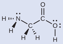
Consider each central atom independently. The electron region geometries:
- nitrogen––four regions of electron density; tetrahedral
- carbon (CH2)––four regions of electron density; tetrahedral
- carbon (CO2)—three regions of electron density; trigonal planar
The local molecular geometry:
- nitrogen––three bonds, one lone pair; trigonal pyramidal
- carbon (CH2)—four bonds, no lone pairs; tetrahedral
- carbon (CO2)—three bonds (double bond counts as one bond), no lone pairs; trigonal planar
Check Your Learning
Another amino acid is alanine, which has the Lewis structure shown here. Predict the electron region geometry and local molecular geometry of the nitrogen atom and the three carbon atoms:
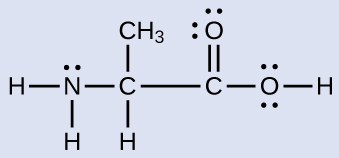
Answer:
electron region geometries: nitrogen––tetrahedral; carbon (CH)—tetrahedral; carbon (CH3)—tetrahedral; carbon (CO2)—trigonal planar
local molecular geometry: nitrogen—trigonal pyramidal; carbon (CH)—tetrahedral; carbon (CH3)—tetrahedral; carbon (CO2)—trigonal planar
Molecular Polarity and Dipole Moment
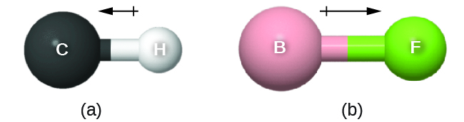
As discussed previously, polar covalent bonds connect two atoms with differing electronegativities, leaving one atom with a partial positive charge (δ+) and the other atom with a partial negative charge (δ–), as the electrons are pulled toward the more electronegative atom. This separation of charge gives rise to a bond dipole moment. This bond dipole moment can be represented as a vector, a quantity having both direction and magnitude (Figure 4). Dipole vectors are shown as arrows pointing along the bond from the less electronegative atom toward the more electronegative atom. A small plus sign is drawn on the less electronegative end to indicate the partially positive end of the bond. The length of the arrow is proportional to the magnitude of the electronegativity difference between the two atoms. For this class, you should memorize these trends of electronegativity: F > O > N > Cl >> … > C > … > H > metals
A whole molecule may also have a dipole moment, depending on its molecular geometry and the polarity of each of its bonds. If the molecule does have a dipole moment, the molecule is said to be a polar molecule; otherwise the molecule is said to be nonpolar. The molecular dipole moment measures the net charge separation in the whole molecule. We determine the molecular dipole moment by adding all of the bond dipole moments in three-dimensional space.
Homonuclear diatomic molecules, such as Br2 and N2, have bond and molecular dipole moments equal to zero, because the two component atoms have equal electronegativity. For heteronuclear molecules, such as CO or HF, the molecular dipole moment is equal to the bond dipole moment, which is determined by the magnitude of difference between the two electronegativity values.
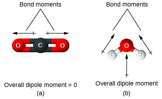
When a molecule contains more than one bond, the geometry must be taken into account. If the bonds in a molecule are arranged such that their bond dipole moments cancel (vector sum equals zero), then the molecule is nonpolar. This is the situation in CO2 (Figure 5). Each of the C=O bonds are polar, but the molecule as a whole is nonpolar. From the Lewis structure and using VSEPR theory, we determine that the CO2 molecule is linear with polar C=O bonds on opposite sides of the carbon atom. The bond dipole moments cancel because they are pointed in opposite directions. In the case of the water molecule (Figure 5), the Lewis structure shows that there are two bonds to a central atom, and the electronegativity difference between oxygen and hydrogen indicates that each of these O-H bonds has a nonzero bond dipole moment. In this case, however, the molecular geometry is bent because of the lone pairs on oxygen, and the two bond dipole moments do not cancel out. Therefore, water does have a net molecular dipole moment and is therefore a polar molecule.
The OCS molecule has a structure similar to CO2, but a sulfur atom has replaced one of the oxygen atoms. To determine if this molecule is polar, we first draw the molecule with the correct geometry. VSEPR theory predicts a linear molecule:
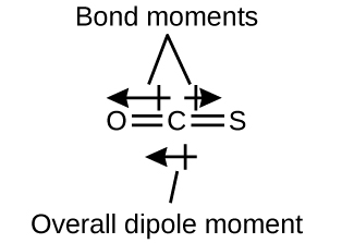
The C-O bond is considerably polar. Although C and S have very similar electronegativity values, S is slightly more electronegative than C, and so the C-S bond is just slightly polar. Even though these bond dipole moments are pointing in opposite directions, they will not fully cancel because they have different magnitudes. Since oxygen is more electronegative than sulfur, the overall molecular dipole moment will point towards the oxygen end of the molecule.
Chloromethane, CH3Cl, is another example of a polar molecule. Although the polar C–Cl and C–H bonds are arranged in a tetrahedral geometry, the C–Cl bond has a larger bond dipole moment than the C–H bonds, and the bond dipole moments do not cancel each other out. All of the dipoles have an upward component in the orientation shown, since carbon is more electronegative than hydrogen and less electronegative than chlorine, giving an overall molecular dipole moment going from the hydrogens through the chlorine:

Note that there is a small electronegativity difference between carbon and hydrogen and a C-H bond is slightly polar; however, the difference is quite small, and C-H bonds are often categorized as nonpolar.
The highly symmetrical molecules BF3 (trigonal planar) and CH4 (tetrahedral), in which all the polar bonds are identical and symmetrical, are nonpolar. The bonds in these molecules are arranged such that their bond dipoles cancel. However, just because a molecule contains identical bonds does not mean that the dipoles will always cancel. Many molecules that have identical bonds and lone pairs on the central atoms have bond dipoles that do not cancel. Examples include H2O, H2S, and NH3. A hydrogen atom is at the positive end and a nitrogen or sulfur atom is at the negative end of the polar bonds in these molecules:

In summary, to be polar, a molecule must:
- Contain at least one polar covalent bond.
- Have a molecular geometry such that the sum of the vectors of each bond dipole moment does not equal zero.
Assignment of Hybrid Orbitals to Central Atoms
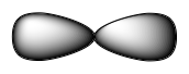
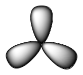
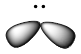
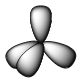
The hybridization of an atom is determined based on the number of regions of electron density that surround it. The geometrical arrangements characteristic of the various sets of hybrid orbitals are shown in Figure 25. These arrangements are identical to those of the electron region geometries predicted by VSEPR theory. VSEPR theory predicts the shapes of molecules, and hybrid orbital theory provides an explanation for how those shapes are formed. To find the hybridization of a central atom, we can use the following guidelines:
- Determine the Lewis structure of the molecule.
- Determine the number of regions of electron density around an atom using VSEPR theory, in which single bonds, multiple bonds, radicals, and lone pairs each count as one region.
- Assign the set of hybridized orbitals from Figure 25 that corresponds to this geometry.
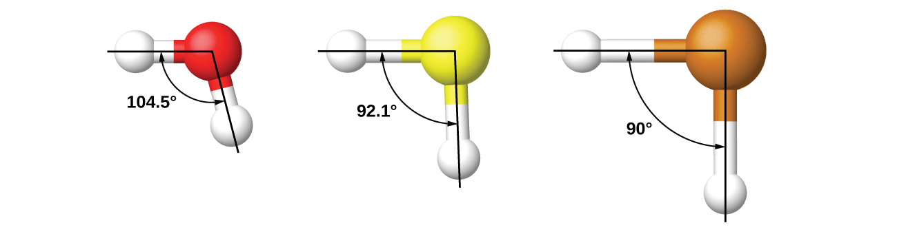
It is important to remember that hybridization was devised to rationalize experimentally observed molecular geometries. The model works well for molecules containing small central atoms, in which the valence electron pairs are close together in space. However, for larger central atoms, the valence-shell electron pairs are farther from the nucleus and there are fewer repulsions. Their compounds exhibit structures that are often not consistent with VSEPR theory and hybridized orbitals are not necessary to explain the observed data. For example, we have discussed the H–O–H bond angle in H2O (in red below), 104.5°, which is more consistent with sp3 hybrid orbitals (109.5°) on the central atom than with 2p orbitals (90°). Sulfur is in the same group as oxygen, and H2S (in yellow) has a similar Lewis structure. However, it has a much smaller bond angle (92.1°), which indicates much less hybridization on sulfur than oxygen. Continuing down the group, tellurium (in brown) is even larger than sulfur, and for H2Te, the observed bond angle (90°) is consistent with overlap of the 5p orbitals, without invoking hybridization. We invoke hybridization where it is necessary to explain the observed structures.
Key Concepts and Summary
In this section, we review many of the topics you are expected to be familiar with that are the foundation of organic chemistry. The first review topic is VSEPR Theory of two, three, and four electron regions. These electron region and molecular geometries enable us to predict molecular shape and bond angles. Using these molecular shapes, we can take a closer look at the electronegative of the atoms within a molecule to predict if a molecule is polar. A molecule’s polarity determines many of its physical properties, like melting point.
Glossary
bond dipole moment
the separation of charge that results when two atoms with differing electronegativites are bonded together, leaving a δ+ charge on the less electronegative atom and a δ- charge on the more electronegative atom
electron region geometry
geometry based on all regions where electrons are located (bonds and lone electron pairs)
hybridization
a widely accepted model that uses quantum mechanics to mathematically combine valence orbitals and create new hybrid orbitals. This model explains the observed bond angles in water, and many other molecules
hybrid orbitals
the new orbitals created after hybridization
molecular (overall) dipole moment
the net charge separation in a molecule
molecular geometry
geometry only based o the location of atoms, not lone electron pairs
nonpolar molecule
a molecule without a dipole moment
polarizability
the measure of how easy or difficult it is for another electrostatic charge (a nearby ion or molecule) to distort a molecule’s electron cloud
polar molecule
a molecule with a dipole moment
valence shell electron-pair repulsion theory (VSEPR theory)
a theory to predict the molecular geometry, including approximate bond angles around a central atom, of a molecule from an examination of the number of bonds and lone electron pairs in its Lewis structure
vector
a quantity having both direction and magnitude