
Unit Five
Day 41: Electrolysis; Commercial Batteries
D41.1 Electrolysis
In an electrolytic cell, supplied electrical energy causes a nonspontaneous redox reaction to occur in a process known as electrolysis. An electrolytic cell is the opposite of a voltaic cell, where a spontaneous redox reaction produces electrical energy.
For example, consider electrolysis of molten sodium chloride. A simplified diagram of the electrolytic cell used for commercial manufacture of sodium metal and chlorine gas is shown in Figure 1. In the molten salt, sodium ions move toward the cathode and chloride ions move toward the anode (note that negative ions move through the circuit in the same overall direction as electrons). A porous screen allows movement of ions but not mixing of the product sodium metal and chlorine gas, which would react spontaneously upon contact.
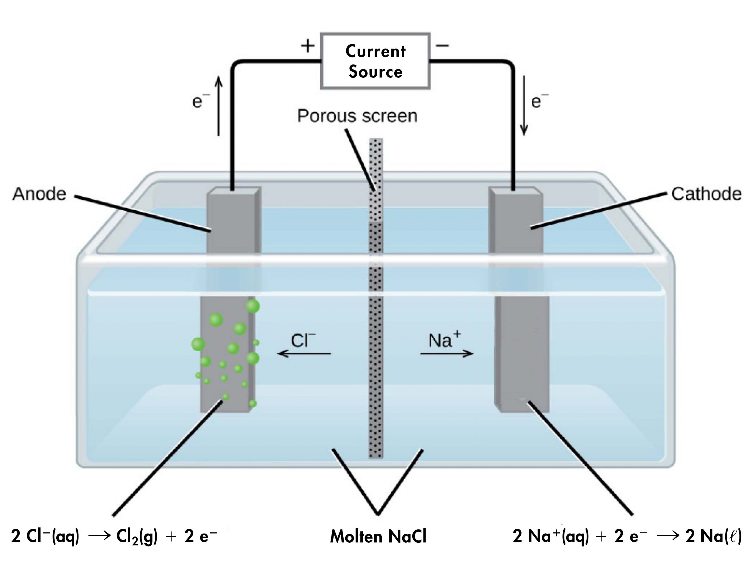
An external source of electric current forces electrons into the electrode in the cathode compartment, forcing the reduction half-reaction to occur:
(At the temperature of molten NaCl, sodium is a liquid, so E°Na+|Na(s) = -2.714 V is an approximation. E°Na+|Na(l) for liquid sodium is not available in the appendix.)
In the anode compartment, the oxidation half-reaction occurs:
The electrons formed here are conducted through a wire to the the positive side of the voltage source, completing the electric circuit.
We can calculate E°cell for this electrolysis cell using the same method we used for voltaic cells; that is,
E°cell = E°right half-cell − E°left half-cell = E°cathode − E°anode = -2.714 V − (+1.358 V) = -4.072 V
The overall reaction is:
The negative E°cell indicates that this reaction is strongly reactant-favored, and under standard-state conditions, the power supply must provide at least 4.1 V to cause the electrolysis reaction to occur. In practice, the applied voltages are higher due to inefficiencies in the process itself and also to help increase the rate of reaction.
With the transition from fossil fuels to renewable energy supplies, an important application of electrolysis is the “splitting” of water into hydrogen gas and oxygen gas (Figure 2). Electric energy from solar panels or wind turbines can be used to synthesize hydrogen for use as a fuel. For current to pass through the solution efficiently, there must be ions present. Hence, acid is typically added to the reaction solution to increase the concentration of ions in solution.
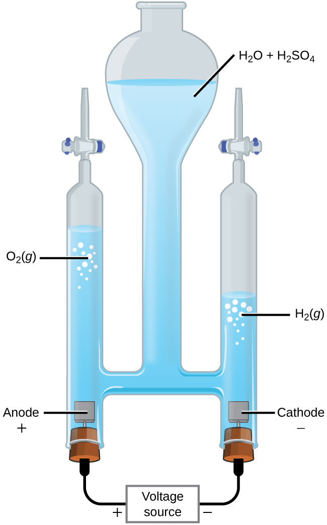
In 1-M acidic solution:
| Oxidation (anode): | 2H2O(l) | ⟶ | O2(g) + 4H+(aq) + 4e‾ | E°anode = +1.229 V |
| Reduction (cathode): | 2 × (2H+(aq) + 2e‾ | ⟶ | H2(g)) | E°cathode = 0 V |
| Overall: | 2H2O(l) | ⟶ | O2(g) + 2H2(g) | E°cell = -1.229 V |
At least 1.229 V is required to make this reactant-favored process occur in 1-M acidic solution.
Finally, consider what occurs during the electrolysis of 1-M aqueous potassium iodide solution at 25 °C. Present in the solution are H2O(l), K+(aq), and I‾(aq). This example differs from the previous examples because more than one species can be oxidized and more than one species can be reduced.
Considering the anode first, the possible oxidation reactions are
| (i) | 2I‾(aq) | ⟶ | I2(s) + 2e‾ | E°anode = +0.535 V |
| (ii) | 2H2O(l) | ⟶ | O2(g) + 4H+(aq) + 4e‾ | E°anode = +1.229 V |
(Oxidation of K+ to K2+ is not considered because K+ has a noble-gas electron configuration and a very high ionization energy, making it very difficult to oxidize. Although I2 is generated in aqueous solution, we approximate the E° by using the value for I2(s).)
Because E°cell = E°cathode – E°anode, the more positive the anode half-cell potential is, the more negative the cell potential would be. Therefore, iodide should be oxidized at the anode because it has a less positive half-cell potential. However, the pH of a 1-M KI solution is 7, so [H+] is far from standard-state conditions. Assuming that O2 is produced at 1 bar, applying the Nernst equation to half-reaction (ii) gives:
(Note that the reaction given in the standard half-cell potential table is the reduction reaction “O2(g) + 4H+(aq) + 4e‾ ⟶ 2H2O(l) E° = +1.229 V”, hence reaction quotient Q is expressed in accordance to the given reaction.)
The Nernst equation shows that Eanode = +0.815 V for reaction (ii) at pH = 7, which is still higher than E°anode for reaction (i). Therefore, reaction (i) is the process that occurs at the anode and I2 forms as a product.
Now consider the possible reactions at the cathode (reduction of I− is not considered because I− has a noble-gas electron configuration and it is not energetically favorable to add more electrons):
| (iii) | 2H2O(l) + 2e‾ | ⟶ | H2(g) + 2OH‾(aq) | E°cathode = -0.8277 V |
| (ii) | K+(aq) + e‾ | ⟶ | K(s) | E°cathode = -2.925 V |
For half-reaction (iii), we again need to apply the Nernst equation to calculate E at pH = 7, assuming H2 is produced at 1 bar:
Hence, reduction of water, with Ecathode = -0.4136 V at pH = 7, is much more likely to occur than reduction of K+(aq) with E°cathode = -2.925 V. (This conclusion is supported by the fact that potassium metal reacts vigorously with water to generate K+(aq), hydrogen gas, and hydroxide ions, so if K(s) formed it would immediately react with water.)
The overall reaction is then:
| Oxidation (anode): | 2I‾(aq) | ⟶ | I2(s) + 2e‾ | E°anode = +0.535 V |
| Reduction (cathode): | 2H2O(l) + 2e‾ | ⟶ | H2(g) + 2OH‾(aq) | Ecathode = -0.4136 V |
| Overall: | 2H2O(l) + 2I‾(aq) | ⟶ | H2(g) + I2(s) + 2OH‾(aq) | Ecell = -0.949 V |
Electroplating
An important use for electrolytic cells is electroplating, which results in a thin coating of metal on top of a conducting surface. Metals typically used in electroplating include cadmium, chromium, copper, gold, nickel, silver, and tin. As an example of electroplating, consider how silver-plated tableware is produced (Figure 3).
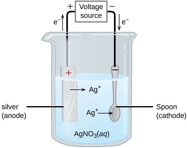
The anode consists of a silver electrode. The cathode is a spoon made from a less expensive metal. Both electrodes are immersed in a solution of silver nitrate. As the potential from the voltage source is increased, current flows. Silver metal is lost at the anode as it goes into solution:
The mass of the cathode increases as silver ions from the solution are deposited onto the spoon:
The net result is the transfer of silver metal from the anode to the cathode. The quality of the electroplated object depends on the thickness of the deposited silver and the rate of deposition.
Quantitative Aspects of Electrolysis
The quantity of current that flows in an electrolytic cell is dictated by the amount (mol) of electrons transferred in a redox reaction, which is in turn related to quantities of reactants and products via reaction stoichiometry. Recall that current, I, is related to the total charge, Q:
Hence:
where F is the Faraday constant.
Exercise 1: Electroplating
D41.2 Commercial Batteries
Many of the devices we use every day, such as laptops and smartphones, are powered by batteries. A battery is an electrochemical cell or series of cells that produces an electric current. In principle, any voltaic cell can be used as a battery. An ideal battery would never run down/drain, produce a constant voltage, and be capable of withstanding environmental extremes of temperature and humidity. Real batteries strike a balance between ideal characteristics and practical limitations.
For example, the mass of a car-starter battery is about 18 kg or ~1% of the mass of an average car. This type of battery would supply nearly unlimited energy if used in a smartphone, but would be completely impractical because of its mass and size. Thus, no single battery is “best” and different batteries are selected for particular applications, keeping things like its mass, cost, reliability, and current capacity in mind.
There are two basic types of batteries: primary and secondary. A few batteries of each type are described next.
D41.3 Primary Batteries
Primary batteries are single-use batteries that cannot be recharged.
Zinc-Carbon Battery
A common primary battery is the dry cell (Figure 4), which is a zinc-carbon battery. The zinc serves as both a container and the negative electrode. The positive electrode is a rod made of carbon that is surrounded by a paste of manganese(IV) oxide, zinc chloride, ammonium chloride, carbon powder, and a small quantity of water.
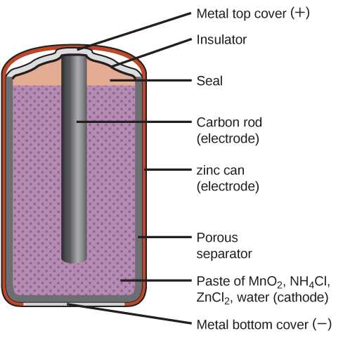
The reaction at the anode can be represented as the oxidation of zinc:
The reaction at the cathode is more complicated, in part because more than one reduction reaction is occurring. The series of reactions that occurs at the cathode is approximately:
The overall reaction for the zinc–carbon battery can be represented as:
The cell potential is about 1.5 V initially, and decreases as the battery is used. As the zinc container oxidizes, its contents eventually leak out, so this type of battery should not be left in any electrical device for extended periods.
The voltage delivered by a battery is the same regardless of the size of a battery. For this reason, D, C, A, AA, and AAA batteries all have the same voltage. However, larger batteries can deliver more moles of electrons and will therefore last longer if powering the same device.
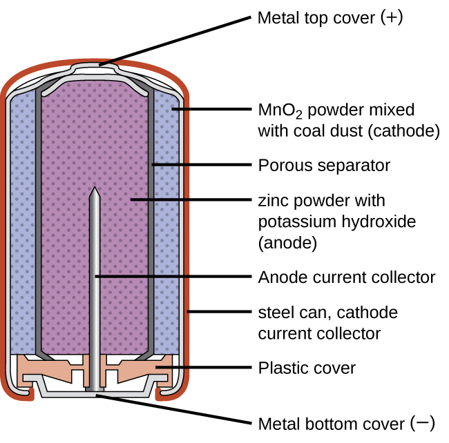
Alkaline Battery
Alkaline batteries (Figure 5) were developed in the 1950s partly to address some of the performance issues with zinc–carbon dry cells, and are manufactured to be their exact replacements. As their name suggests, these types of batteries use alkaline electrolytes, often potassium hydroxide.
The reactions are:
| Oxidation (anode): | Zn(s) + 2OH‾(aq) | ⟶ | ZnO(s) + H2O(l) + 2e‾ | E°anode = -1.28 V |
| Reduction (cathode): | 2MnO2(s) + H2O(l) + 2e‾ | ⟶ | Mn2O3(s) + 2OH‾(aq) | E°cathode = +0.15 V |
| overall: | Zn(s) + 2MnO2(s) | ⟶ | ZnO(s) + Mn2O3(s) | E°cell = +1.43 V |
An alkaline battery can deliver about three to five times the energy of a zinc-carbon dry cell of similar size. Alkaline batteries sometimes leak potassium hydroxide, so these should also be removed from devices for long-term storage. While some alkaline batteries are rechargeable, most are not. Attempts to recharge an alkaline battery that is not rechargeable often leads to rupture of the battery and leakage of the potassium hydroxide electrolyte.
D41.4 Secondary Batteries
Secondary batteries are rechargeable; that is, the reaction that powers the battery can be reversed so that the original reactants can be regenerated. Secondary batteries are found in smartphones, electronic tablets, automobiles, and many other devices.
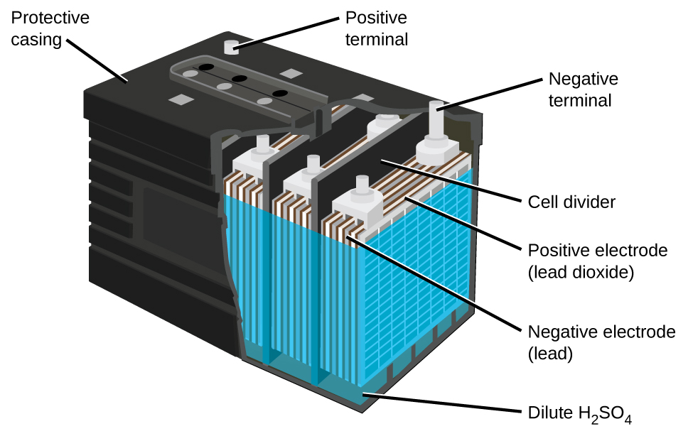
Lead-Acid Battery
The lead-acid battery (Figure 6) is the type of secondary battery used to start gasoline-powered automobiles. It is inexpensive and capable of producing the high current required by the starter motors when starting a car. They are heavy because of lead’s high density, they contain highly corrosive concentrated sulfuric acid, and must be disposed of properly to avoid lead-poisoning hazards. But they can produce a lot of current in a short time so for certain applications they are the best choice.
The reactions for a lead acid battery are:
| Oxidation (anode): | Pb(s) + HSO4‾(aq) | ⟶ | PbSO4(s) + H+(aq) + 2e‾ | E°anode = -0.359 V |
| Reduction (cathode): | PbO2(s) + HSO4‾(aq) + 3H+(aq) + 2e‾ | ⟶ | PbSO4(s) + 2H2O(l) | E°cathode = +1.690 V |
| overall: | Pb(s) + PbO2(s) + 2H2SO4(aq) | ⟶ | 2PbSO4(s) + 2H2O(l) | E°cell = +2.049 V |
Each cell produces 2.05 V, so six cells can be connected in series to produce a 12-V car battery.
In each cell, the lead electrodes are immersed in sulfuric acid. The anodes are spongy lead metal and the cathodes are lead impregnated with lead oxide. As the battery is discharged, a powder of PbSO4 forms on the electrodes. When a lead-acid battery is recharged by a car’s alternator, electrons are forced to flow in the opposite direction which reverses the reactions at anode and cathode, in other words, the cell undergoes electrolysis reactions to replenish the substances that have reacted away.
Practically, the concentrated sulfuric acid becomes quite viscous when the temperature is low, inhibiting the flow of ions between the plates and reducing the current that can be delivered. This effect is well-known to anyone who has had difficulty starting a car in cold weather. These batteries also tend to slowly self-discharge, so a car left idle for several weeks might be unable to start. And after thousands of discharge-charge cycles, PbSO4 that does not get converted to PbO2 gradually changes to an inert form which limits the battery capacity. Also, “fast” charging causes rapid evolution of potentially explosive H2 gas from the water in the electrolyte (electrolysis of water); the gas bubbles form on the lead surface and can tear PbO2 off the electrodes. Eventually enough solid material accumulates at the bottom of the electrolyte to short-circuit the battery, leading to its permanent demise.
Exercise 2: Lead-acid Batteries
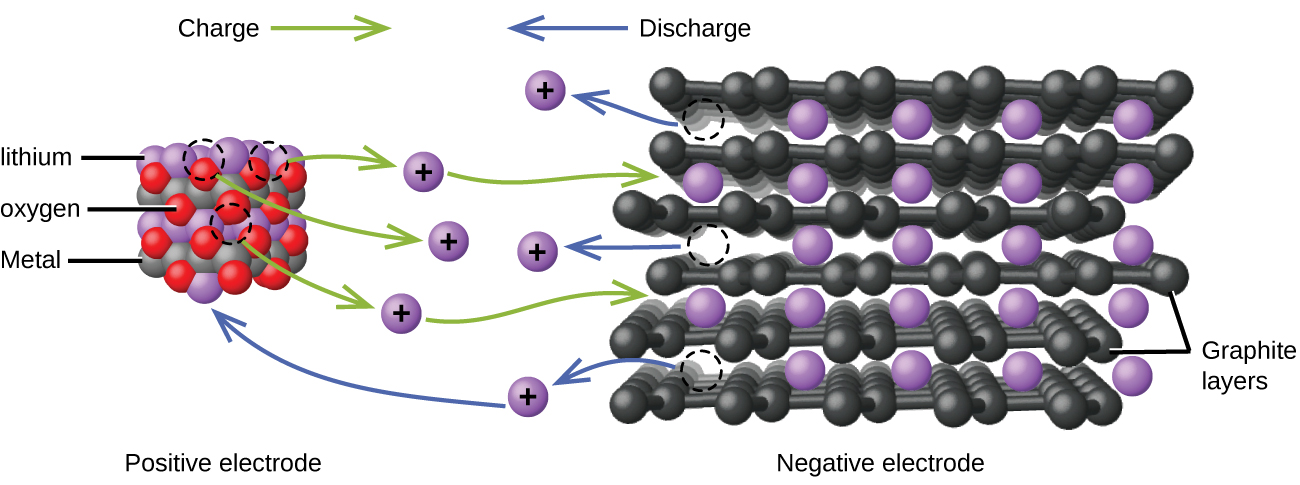
Lithium Ion Battery
Lithium ion batteries (Figure 7) are among the most popular rechargeable batteries and are used in many portable electronic devices because their advantages outweigh the disadvantage of higher cost. In a typical Li-ion battery the reactions are:
| Oxidation (anode): | LiCoO2 | ⟶ | Li1-xCoO2 + xLi+ + xe‾ |
| Reduction (cathode): | xLi+ + xC6 + xe‾ | ⟶ | xLiC6 |
| overall: | LiCoO2 + xC6 | ⟶ | Li1-xCoO2 + xLiC6 |
(x is no more than about 0.5.) The battery voltage is about 3.7 V.
Lithium batteries are popular because they can provide a large amount of current, are lighter than comparable batteries of other types, produce a nearly constant voltage as they discharge, and only slowly lose their charge when stored.
Exercise 3: Lithium-Ion Batteries
D41.5 Fuel Cells
Suppose a voltaic cell is constructed such that the substance that is oxidized at the anode and the substance that is reduced at the cathode (the reactants in the overall redox reaction) are both supplied continuously. Such a battery would never run down because reactant concentrations or partial pressures would never decrease. Such a device is a fuel cell, which produces electricity as long as fuel is available. Hydrogen fuel cells have been used to supply power for satellites, space capsules, automobiles, boats, and submarines (Figure 8).
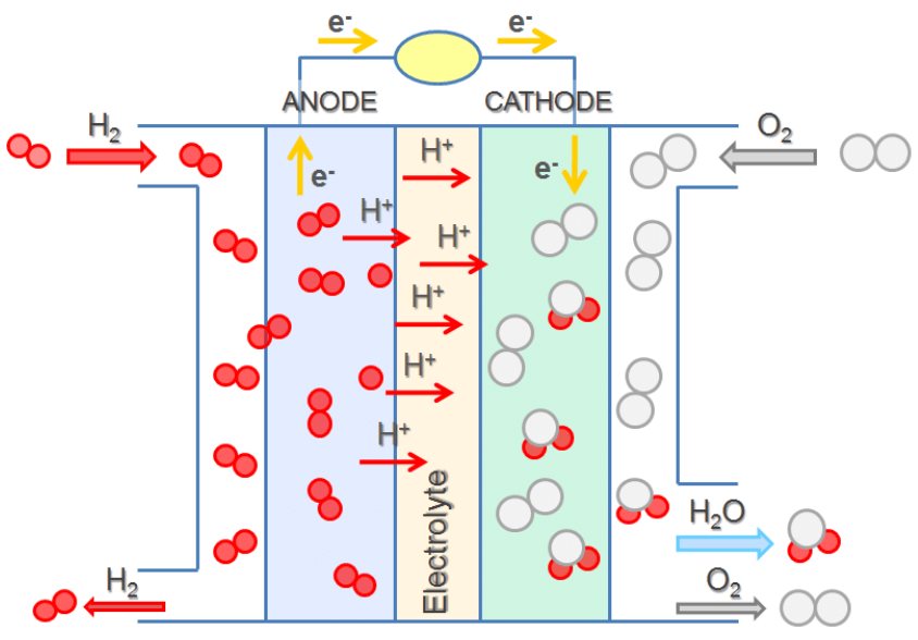
In a hydrogen-oxygen proton-exchange fuel cell, the cell potential is about 1 V, and the reactions involved are:
| Oxidation (anode): | 2 × (H2(g) | ⟶ | 2H+(aq) + 2e‾) |
| Reduction (cathode): | O2(g) + 4H+(aq) + 4e‾ | ⟶ | 2H2O(l) |
| overall: | O2(g) + 2H2(g) | ⟶ | 2H2O(l) |
The efficiency of fuel cells is typically about 40-60%, which is higher than the typical internal combustion engine (25-35%). Moreover, in the case of the hydrogen fuel cell, nearly pure water is produced as exhaust. Currently, fuel cells are comparably more expensive and contain features that may cause a higher failure rate.
Podia Question
Consider this graph, which shows cell potential on the vertical axis and fraction of reactants remaining (battery life remaining) on the horizontal axis for a commercial battery.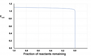
- Write an explanation in appropriate scientific language for why the graph has the shape it has.
- Describe why the shape of this graph is a positive feature when batteries power devices such as smartphones and laptop computers.
Two days before the next whole-class session, this Podia question will become live on Podia, where you can submit your answer.
