
Unit Two
Day 9: Bond Properties; Valence Bond Theory
D9.1 Bonds, Molecules, and Structures
In a molecule, atoms are connected by covalent bonds that result from overlap of atomic orbitals. Molecules can consist of a small or large number of atoms and may involve all the same kind or a dozen different kinds of atoms. The atoms can be connected by bonds in a variety of different ways, so there is a broad range of different molecular structures. Thus, there are many things a chemist needs to know about a molecule:
- What kinds of atoms and how many of each are in the molecule?
- Which atoms are bonded to which other atoms?
- What are the bond lengths between atoms?
- How strong are the bonds?
- What are the angles between the bonds?
- How are the atoms arranged in three-dimensional space?
- What kinds of attractions are there between molecules?
- How strong are the attractions between molecules?
- Are there noncovalent attractive forces within a large molecule, holding one part of the molecule to another?
At this point we have introduced the first four of these, using molecular formulas, Lewis structures, atomic radii/bond lengths, and bond enthalpies. For example, in a water molecule, the molecular formula H2O indicates that there are two H atoms and one O atom. A Lewis structure, H–O–H shows that both H atoms are bonded to the O atom. The O–H bond length (94 pm) and bond enthalpy (467 kJ/mol) verify that the bonds are strong—separating the atoms is difficult.
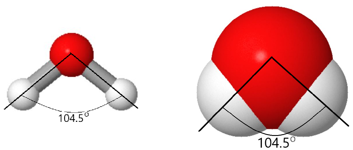
But there is more to a water molecule than that. A ball-and-stick or space-filling model shows that the angle between the two O–H bonds is 104.5°—somewhat more than a right angle. Angles larger or smaller than 104.5° result in higher energy (lower stability). As a result of the shape and type of atoms in the water molecule, there are stronger forces between water molecules than between methane (CH4) molecules, although both contain the same number of electrons.
As the number of atoms in a molecule increases the last four factors in the list above become more and more important. You will learn about them throughout this Unit, beginning with additional properties of chemical bonds in the next sections.
D9.2 Bond Polarity
If the two atoms that form a covalent bond are identical, as in H2 or Cl2, then the electrons in the bond must be shared equally between the two atoms. In a pure covalent bond, shared electrons have an equal probability of being near each nucleus.
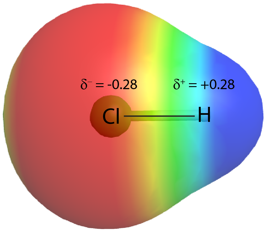
On the other hand, if the two atoms are different, they may have different attractions for the shared electrons. When the bonding electrons are attracted by one atom more than the other atom the bond is called a polar covalent bond. For example, in HCl, the Cl atom attracts the bonding pair of electrons more than the H atom does, and electron density of the H–Cl bond is shifted toward the chlorine atom. Quantum mechanics calculations show that the chlorine atom, which has 17 protons, has electron density equivalent to 17.28 electrons and therefore a partial negative charge, δ– = −0.28. The hydrogen atom has a partial positive charge, δ+ = +0.28.
This unequal distribution of electron density on two bonded atoms produces a bond dipole moment, the magnitude of which is represented by µ (Greek letter mu). The dipole moment is equal to:
μ = Qr
where Q is the magnitude of the partial charges (for HCl this is 0.28 times the charge of an electron) and r is the distance between the charges (the bond length). Bond dipole moments are measured in units of debyes (D); 1 D = 3.336 × 10⁻³⁰ coulomb meter.
The bond dipole moment has both direction and magnitude and can be represented as a vector (Figure 3). A dipole vector is drawn as an arrow, with the arrowhead pointing to the partially negative end, and a small + sign on the partially positive end. The length of the arrow is proportional to the magnitude of the dipole moment.

D9.3 Electronegativity
The polarity of a covalent bond is determined by the difference between the electronegativities of the bonded atoms. Electronegativity (EN) is the tendency of an atom in a molecule to attract bonding electron density. Thus, in a bond, the more electronegative atom is the one with the δ− charge.
The greater the difference in electronegativity between two bonded atoms is, the larger the shift of electron density in the bond toward the more electronegative atom is. Greater electronegativity difference, greater Δ(EN), gives larger partial charges on the atoms. Electronegativity values for most elements are shown in the periodic table in Activity 1; they also are tabulated in the appendix.
Electronegativity, Electron Affinity, and Ionization Energy
These three properties are all associated with an atom gaining/losing electrons. Electron affinity and ionization energy are experimentally measurable physical quantities.
Electron affinity (EA) is the energy change when an isolated gas-phase atom acquires an electron; it is usually expressed in kJ/mol.
Ionization energy (IE) is the energy that must be transferred to an isolated gas-phase atom to remove an electron; it is also typically expressed in kJ/mol.
Electronegativity describes how strongly an atom attracts electron density in a bond. It is calculated, not measured, has an arbitrary relative scale, and has no units.
Electronegativity and Bond Type
The difference in electronegativity, Δ(EN), of two bonded atoms provides a rough estimate of polarity of the bond, and thus of the bond type. When Δ(EN) is very small (or zero), the bond is covalent and nonpolar. When Δ(EN) is large, the bond is polar covalent or ionic. (In a joined pair of ions, such as Na+Cl−, there is nearly complete transfer of valence electrons from one atom to another to produce a positive ion and a negative ion. The Na+ and Cl− ions form a dipole with δ+ approximately equal to +1 and δ− approximately −1.)
Δ(EN) spans a continuous scale and serves as a general guide; there is no definitive cutoff that defines a bond type. For example, HF has Δ(EN) = 1.8 and is considered a polar covalent molecule. On the other hand, NaI has a Δ(EN) of 1.7 but forms an ionic compound. When considering the covalent or ionic character of a bond, you should also take into account the types of atoms involved and their relative positions in the periodic table. Bonds between two nonmetals are usually described as covalent; bonding between a metal and a nonmetal is often ionic.
Some compounds contain both covalent and ionic bonds. For example, potassium nitrate, KNO3, contains the K+ cation and the polyatomic NO3− anion, which has covalent bonds between N and O.
Exercise 1: Polarity and Electronegativity Difference
Exercise 2: Bond Polarity and Electronegativity
D9.4 Formal Charge
It is useful to consider how valence electrons are distributed in a molecule. Formal charge, the charge an atom would have if the electron density in the bonds were equally shared between the atoms, is one way to do this. For each atom in a Lewis structure, half of the electrons in bonds are assigned to the atom, and all lone-pair electrons (which are not shared with other atoms) are assigned to the atom.
An atom’s formal charge is calculated as the difference between its number of valence electrons (in the unbonded, free atom) and its assigned number of electrons in the molecule:
- If the assigned number of electrons equals the number of valence electrons, the atom has zero formal charge.
- If the assigned number of electrons exceeds the number of valence electrons, the atom has a negative formal charge.
- If the assigned number of electrons is less than the number of valence electrons, the atom has a positive formal charge.
Because formal charge counts all valence electrons in a molecule, the sum of the formal charges of all the atoms in a molecule or ion must equal the actual charge of the molecule or ion.
The formal charge for any given atom is not the same as its actual partial charge, such as those calculated in Section D9.2 above. This is because formal-charge calculations assume all covalent bonds are nonpolar, which is seldom the case except for homonuclear molecules.
Exercise 3: Formal Charge from Lewis Structure
Exercise 4: Formal Charge from Lewis Structure
Using Formal Charge to Predict the Most Likely Lewis Structure
While formal charges do not portray the true electron density distribution within a molecule, they nonetheless account for electron arrangement in a Lewis structure in units of a whole electron. Therefore, if following the steps for drawing Lewis structures lead to more than one possible arrangement of electrons and/or atoms for a given molecule, formal charges can help to decide which arrangement is likely to be the most stable, and hence the most likely Lewis structure for the given molecule.
- For an uncharged molecule, a Lewis structure in which all atoms have a formal charge of zero is preferable.
- The fewer atoms with nonzero formal charges, the better.
- The smaller the magnitude of the formal charges, the better.
- A Lewis structure with formal charges of the same sign (both + or both −) on adjacent atoms is less likely.
- Lewis structures with negative formal charges on more electronegative atoms are preferable.
For example, consider these three possible Lewis structures of carbon dioxide, CO2:
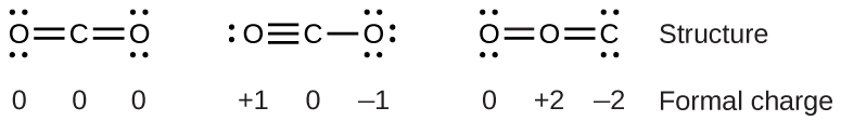
All structures have octets on each atom, but the structure on the left is preferable because all atoms have zero formal charge. The structure on the right is least likely because of the larger formal charges.
Exercise 5: Formal Charge and Lewis Structure
D9.5 Resonance Structures
In a single Lewis structure, a pair of electrons can only be depicted as shared between two atoms or localized to a single atom. However, as mentioned in Section D6.3, the molecular orbitals of a polyatomic molecule often span the entire molecule. For example, such delocalized electron distributions in π bonds can have a direct effect on molecular properties and chemical reactivity. Therefore, it is important to be able to use Lewis structures to indicate electron delocalization.
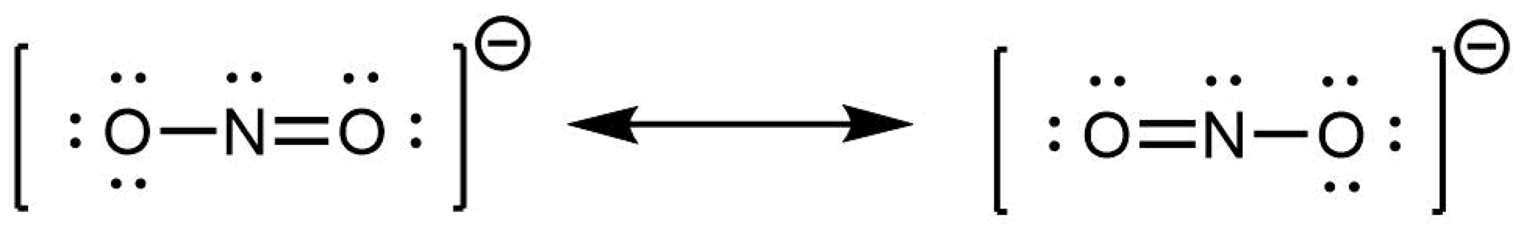
For example, two Lewis structures can be drawn for the nitrite anion, NO2−, both of which satisfy the guidelines for the best Lewis structure for NO2‾:
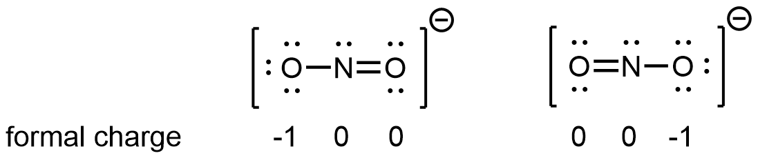
Note that in these two Lewis structures, each of the three atoms is in the same position. The difference is in the location of electrons. In other words, these two Lewis structures convey the idea that the π bond may be between left O and central N or between central N and right O.
If the NO2‾ molecule were correctly described by either one of the Lewis structures, we would expect one N-O bond to be longer than the other. However, experiments show that both bonds in NO2− are the same length. Moreover, the bonds are longer than a N=O double bond and shorter than a N-O single bond. Hence, neither Lewis structure is a correct depiction of the actual molecule, and the best representation of NO2− is an average of these two Lewis structures.
When the actual distribution of electrons is a weighted average of a set of Lewis structures, those Lewis structures are called resonance structures. The actual electronic structure of the molecule (the average of the resonance forms) is called a resonance hybrid. A double-headed arrow between Lewis structures indicates that resonance structures are being depicted:
A molecule does not fluctuate between resonance structures; rather, the actual electronic structure is always the weighted average of the resonance structures. In other words, a single Lewis structure is insufficient to correctly represent the molecule (a shortcoming of a simple diagram), and a set of resonance structures (a resonance hybrid) is a better representation of electron density distribution in the molecule.
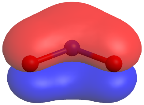
In the specific case of NO2‾, the two resonance structures above are needed to correctly depict two π-bond electrons that are delocalized over the entire molecule (click on the image below for a rotatable 3D view of the π molecular orbital occupied by these two electrons):
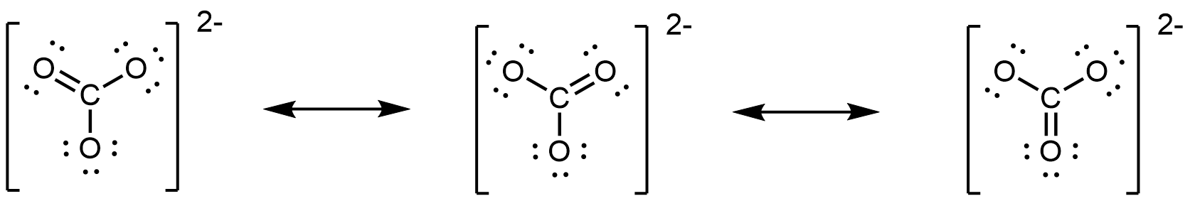
The carbonate anion, CO32−, provides another example of insufficiency of a single Lewis structure and the need for a set of resonance structures:
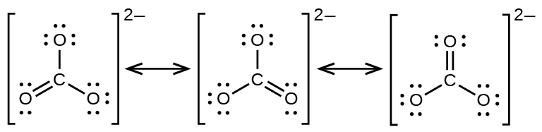
Experiments show that all three C–O bonds are exactly the same. In other words, the two electrons in the π bond are delocalized over the entire molecule, as opposed to being only between one oxygen atom and the carbon atom.
To summarize, in a single Lewis structure, bonding (σ or π) is always between two atoms. Hence, two or more Lewis structures are needed to properly describe a molecule with delocalized electrons (spread over three or more atoms). When drawing a set of resonance structures:
- Each resonance structure should have the same number of electrons.
- Total formal charge is a useful tool for checking the number of electrons.
- Between resonance structures, atom locations are fixed: only the electrons move.
- The skeleton structure of the molecule remains the same in all resonance structures.
- However, you can draw a set of resonance structures in any perspective. For example, you could also draw the CO32− resonance structures as
- Double-headed arrows between Lewis structures communicate that what is drawn is a set of resonance structures.
In NO2‾, the two major resonance structures contribute equally to the resonance hybrid. Similarly, the three major resonance structures of CO32− contribute equally to the resonance hybrid. However, it is possible for some structures in a resonance hybrid to be more important than others. For example, consider these three resonance structures of cyanate ion (OCN–):
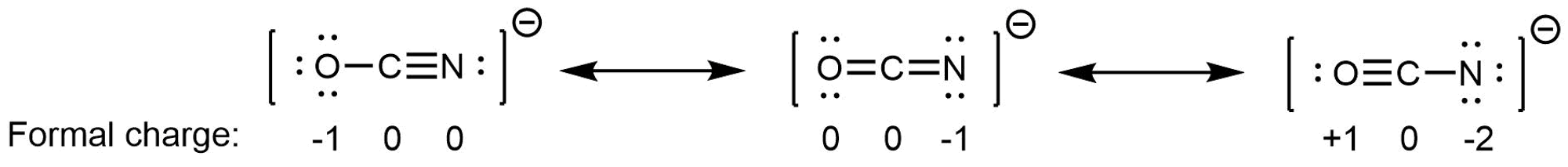
The atoms in each resonance structure have a full octet, but they differ in their formal charges. This implies that certain electron arrangements may be a bit more stable than others, and hence they do not contribute equally to the resonance hybrid.
From the formal-charge rules, we can estimate that the resonance structure on the right would contribute the least; that arrangement of electrons is the least stable of the three. The resonance structure on the left would contribute more than the middle structure because it has the -1 formal charge on the more electronegative O atom. (For OCN–, high level quantum mechanics calculations show that the left structure contributes 61% to the resonance hybrid, the middle structure contributes 30%, and the right resonance structure contributes only 4%.)
D9.6 Aromatic Molecules
Benzene, C6H6, is representative of a large number of aromatic compounds. These compounds contain ring structures and exhibit bonding that must be described using resonance structures. The resonance structures for benzene are:
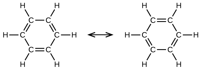
All six C-C bonds are equivalent and exhibit bond lengths that are intermediate between those of a C–C single bond and a C=C double bond.
The chemical reactivity of aromatic compounds differs from the reactivity of alkenes. For example, aromatic compounds do not undergo addition reactions. Instead, with the aid of a catalyst, they can undergo substitution reactions where one of the hydrogen atoms is replaced by a substituent: another atom or group of atoms. A substitution reaction leaves the delocalized double bonds intact.
D9.7 Valence Bond Theory
Lewis structures are easy-to-draw, planar representations of bonding in molecules. They help us to figure out and think about which atoms are bonded to which and whether bonds are single or multiple. However, by default, they do not represent the 3D geometry of a molecule, nor the molecular orbitals (MOs) that determine electron-density distributions.
You have probably used VSEPR to predict the 3D shapes of molecules. VSEPR involves counting electron regions (pairs) around a central atom, assuming that electron regions repel and stay as far apart as possible, and bonding terminal atoms to electron regions. VSEPR is often good at predicting the arrangement of bonds around an atom, and it is OK to use it to predict idealized linear, trigonal planar, and tetrahedral arrangements of bonds that you will encounter in this course, but VSEPR has significant limitations:
- VSEPR has little or no basis in modern quantum theory; you have just spent significant time studying quantum theory and we want you to be able to use that experience.
- It is often difficult to apply VSEPR to molecules described by two or more resonance structures (that is, molecules with delocalized electrons). Thus VSEPR makes it more difficult to understand many molecular structures—for example, structures of protein molecules.
- VSEPR assumes that lone pairs occupy more space than bond pairs, but there is no evidence, experimental or theoretical, to support that assumption; in fact, there is some evidence to the contrary.
- VSEPR assumes that all lone pairs are equivalent, but there is experimental evidence that they are not. For example, the two lone pairs in a water molecule do not have the same ionization energy and do not have equivalent probability distributions (Journal of Chemical Education 1987, Vol. 64, pp 124-128.).
- VSEPR often cannot explain relative bond angles. For example, why is the H-P-H angle in PH3 93.5° while the H-N-H angle in NH3 is 107.5°? (If the decrease in bond angle from the tetrahedral angle of 109.5° to 107.5° for NH3 is due to a “fatter” lone pair, why does the angle decrease so much more for the larger P atom? A “fatter” lone pair should be less likely to repel the other bonds because they are farther apart.)
For these reasons, VSEPR is a model that has limited applicability. In this course we will use a better model—valence bond theory—which is consistent with modern quantum theory, makes more accurate and more comprehensive predictions than VSEPR, and is a better basis for understanding more advanced bonding topics. If you want to, it is OK to use VSEPR to predict idealized shapes, but applying the ideas presented in this section and sections D10.1 through D10.6 will allow you to describe structures with delocalized electrons better and predict bond angles more accurately.
Valence bond theory is a model that focuses on the formation of individual chemical bonds, such as the formation of a σ bond between two atoms within a polyatomic molecule. Like molecular orbital theory, valence bond theory deals with how atomic orbitals (AOs) change and combine when a molecule forms, but instead of forming MOs that span the whole molecule, valence bond theory combines valence orbitals of each atom individually so that the combination gives stronger bonding in specific directions. Hence, valence bond theory allows us to derive idealized 3D geometries for molecules based only on their Lewis structures, without having to perform any computation.
Valence bond theory uses the extent of orbital overlap to infer the strengths of chemical bonds: greater overlap leads to bonds that are stronger and hence a molecule that is more stable. For a given atom in a molecule, overlap with orbitals on other atoms can be greater when some or all of the atom’s AOs form hybrid orbitals. Hybrid orbitals are combinations of valence atomic orbitals that emphasize concentration of electron density in specific directions. A hybrid orbital’s greater electron density in a specific direction provides greater overlap with an orbital from another atom when forming a σ bond.
For an example of how orbital hybridization works, consider combining a single 2s AO with a single 2p AO, both on the same atom (Figure 4). The 2s AO is spherically symmetric, so it has the same phase (mathematical sign) on either side of the nucleus, but the 2p AO changes sign at the nucleus. Thus, on one side of the nucleus, the 2s and 2p AOs are in phase, while on the other side they are out of phase.
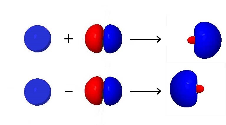
If we add the two AOs, the new hybrid orbital will be larger on the side where the AOs are in phase and smaller on the other side where the AOs are out of phase. If we subtract them, the resultant hybrid orbital will be larger on the side where the AOs are out of phase and smaller where they are in phase. Hence, from one 2s AO and one 2p AO, we can derive two sp hybrid orbitals.
Activity 3: Orbital Hybridization
Day 9 Pre-class Podia Problem: Covalent Bonds
1. Consider these chemical bonds:
C–H C=C C–C C–Br C–F
Choose a pair of bonds from the list, predict which is longer, and write an explanation of your prediction.
Choose a pair of bonds from the list, predict which is stronger, and write an explanation of your prediction.
Choose a pair of bonds from the list, predict which is more polar, and write an explanation of your prediction.
2. NO is a molecule with an odd number of electrons. Write a Lewis structure for NO. Are there resonance structures? Is one resonance structure more dominant than another? If so, identify the more dominant structure and explain why it is more dominant.
Two days before the next whole-class session, this Podia question will become live on Podia, where you can submit your answer.
