
Unit One
Day 6: Molecular Orbitals; Lewis Structures
D6.1 Second-Row Diatomic Molecules
Let’s consider some slightly more complex examples of molecular orbitals. F2, O2, and N2 are diatomic molecules formed by elements from the second row of the periodic table. These molecules contain many more electrons than H2, and their molecular orbitals are derived from p atomic orbitals as well as s atomic orbitals.
Exercise 1: Shapes and Phases of p Atomic Orbitals
Additional Practice
Now think about what happens when two atoms containing 2p atomic orbitals approach each other. Assume that the internuclear axis is the z axis. This means that the 2pz atomic orbitals are aligned along the internuclear axis while the 2px and 2py atomic orbitals are oriented perpendicular to the internuclear axis.
When the two atoms approach, the bonding and antibonding overlap of the two 2pz atomic orbitals occurs along the internuclear axis (z axis):
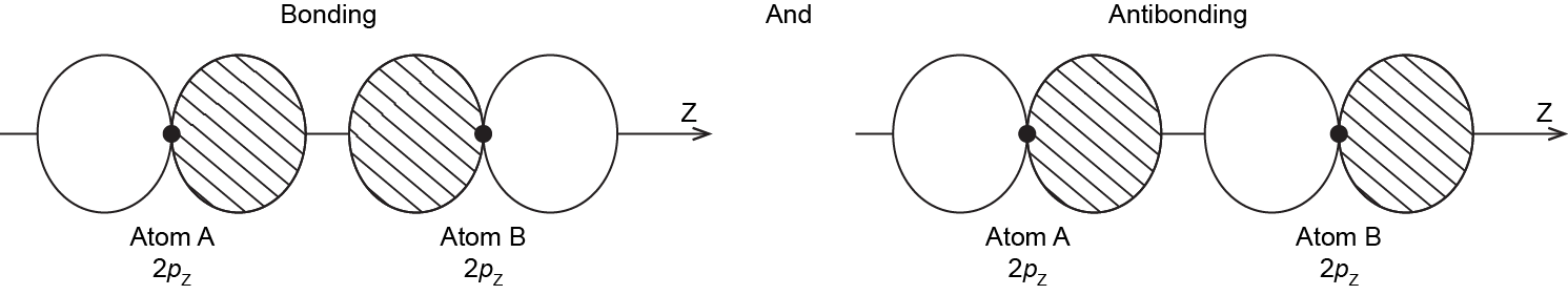
MOs derived from these two combinations are labeled [latex]\sigma_{\text{2}p_\text{z}}[/latex] and [latex]\sigma^*_{\text{2}p_\text{z}}[/latex]. If you don’t understand why these MOs are have the label σ, review Section D5.5.
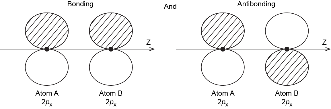
It is also possible to make bonding and antibonding combinations from the two 2px AOs and from the two 2py AOs. Here is a diagram for the two ways the 2px AOs can overlap. Notice that the orbitals overlap side-by-side, not end-on, because the 2px AOs are aligned perpendicular to the internuclear axis (z axis).
Exercise 2: Molecular Orbitals Involving p Atomic Orbitals
Additional Practice
When two 2p AOs overlap side-by-side, the bonding MO formed is not symmetric with respect to rotation around the internuclear axis. Thus, the bond formed is not a σ bond. If you look down the internuclear (bond) axis, the “side view” of the MO looks similar to a 2p atomic orbital; this MO is called a π orbital.

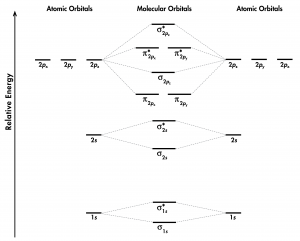
Think about all atomic orbitals that are occupied in a fluorine atom, F: 1s, 2s, 2pz, 2px, and 2py. For each pair of AOs (such as 2s on atom A with 2s on atom B), overlap produces one bonding and one antibonding MO. There is σ and σ* for 1s – 1s, 2s – 2s, and 2pz – 2pz overlaps. There is π and π* for 2px – 2px, and 2py – 2py overlaps. These ideas result in the MO energy-level diagram shown here:
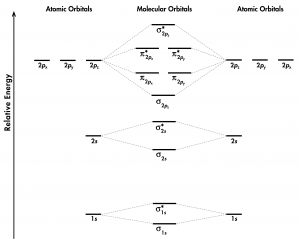
From the ten AOs (five from each F atom), ten MOs are formed in F2. Note that whether a MO is bonding or antibonding is dependent on whether it is lower or higher in energy than the AOs from which it is derived. Hence, even though [latex]\sigma^*_{\text{1}s}[/latex] is lower in energy than [latex]\sigma_{\text{2}s}[/latex], it is still an antibonding MO.
We also see in Figure 1 that the two π bonding MOs, [latex]\pi_{\text{2}p_\text{x}}[/latex] and [latex]\pi_{\text{2}p_\text{y}}[/latex], are degenerate (have the same energy). This is because the side-by-side overlap of two 2px AOs is identical to the side-by-side overlap of two 2py AOs. They differ only in that [latex]\pi_{\text{2}p_\text{x}}[/latex] and [latex]\pi_{\text{2}p_\text{y}}[/latex] are perpendicular to each other, because the 2px AO is perpendicular to the 2py AO. Similar reasoning leads to the conclusion that the [latex]\pi^*_{\text{2}p_\text{x}}[/latex] and [latex]\pi^*_{\text{2}p_\text{y}}[/latex] MOs are also degenerate. Recognizing degenerate MOs is important when applying Hund’s rule to determine molecular electron configurations.
Figure 2 shows the formation of the two perpendicular π bonds as two N atoms approach each other. (The two molecular depictions in the figure represent the same N2 molecule: one shows the 2px – 2px orbital overlap and the other shows the 2py – 2py orbital overlap.)
Exercise 3: Molecular Orbital Electron Configurations
Additional Practice
Based on the electron configuration for the F2 molecule, the π and π* MOs are all filled; there is no net π bond in the molecule. This is reflected in the bond order calculation: F2 has a bond order of 1, corresponding to a single σ bond.
D6.2 Bond Length and Bond Enthalpy
Formation of a stable covalent molecule involves sharing electrons between two or more nuclei (the electrons occupy molecular orbitals that increase electron density between nuclei). The bond length between any two adjacent nuclei in such a covalent molecule is the distance between the two nuclei at the minimum energy in a graph of energy versus nuclear separation. For example, the bond length in a H2 molecule is 74 pm, as shown in Figure 3.
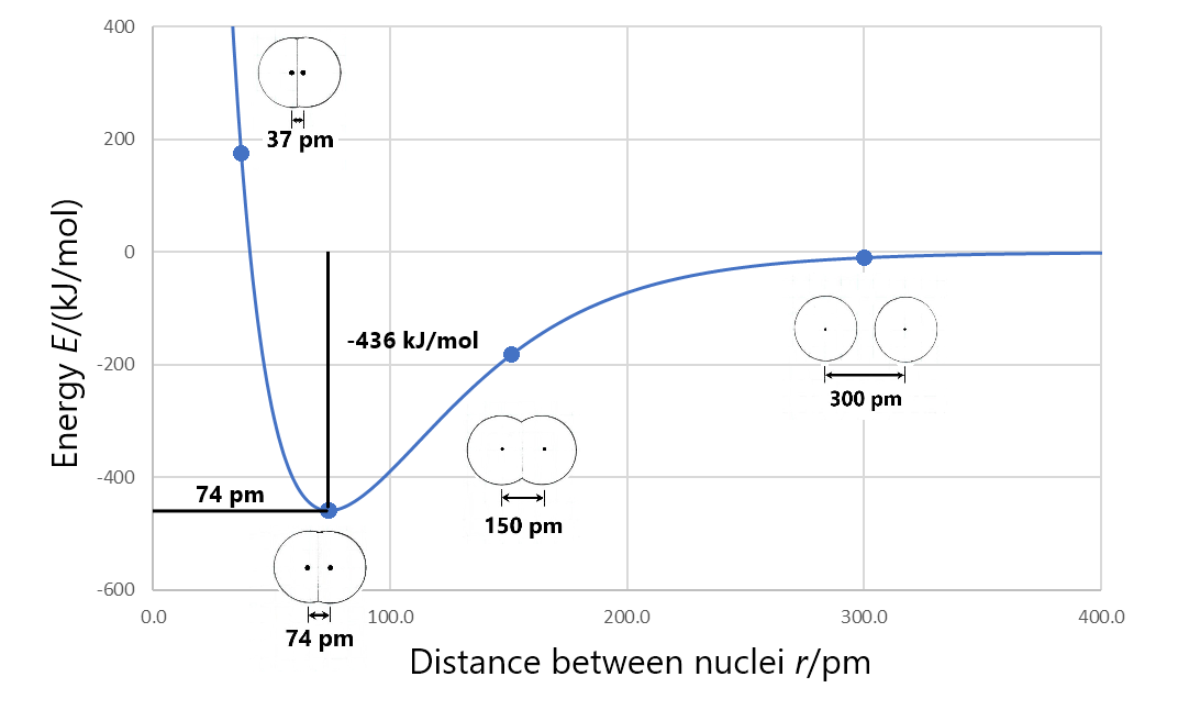
Bond enthalpy (also called bond energy) is the enthalpy change when a chemical bond is broken; that is, when two bonded atoms are completely separated. For example, Figure 3 shows that the bonded hydrogen atoms have energy of −436 kJ/mol relative to the separated hydrogen atoms. This means that the energy of the molecule must be increased by 436 kJ/mol to separate the atoms (break the bond). So the bond enthalpy for H2 is 436 kJ/mol.
Exercise 4: Bond Enthalpy
Lengths of single bonds can be roughly estimated by using the covalent radii of the bonded atoms. For example, adding the covalent radius of C (77 pm) to that of O (74 pm), estimates the length of a C—O bond to be 151 pm. This is quite close to the average C—O bond length of 143 pm. (Both of these values are estimates because covalent radii and bond lengths are averaged over many molecules and therefore are not exact for any specific molecule.)
In general, the bigger the atoms are, the longer the bond between them is. For example, consider the following trend in the average C-X bond lengths, where X is a halogen:
| C-F | 141 pm |
| C-Cl | 176 pm |
| C-Br | 191 pm |
| C-I | 210 pm |
Bond lengths are also dependent on bond order. For example, the C—C single bond has an average length of 154 pm, while a C=C double bond is 134 pm long, and a C≡C triple bond has an average length of 121 pm.
Exercise 5: Bond Length and Atomic Radius
Comparisons of the average bond length and bond enthalpy values show a general trend: a covalent bond with a shorter bond length generally has a larger bond enthalpy.
D6.3 Bonding in Molecules with More Than Two Atoms
Molecules with three or more atoms have molecular orbitals that span the entire molecule. The MOs are derived from the overlap of AOs from all the atoms in the molecule. Both the MO wave functions and the structure of the energy-level diagram are much more complicated than for diatomic molecules, but mathematical techniques exist for calculating and displaying the electron densities that form chemical bonds. In this course we will not delve deeply into these more complicated cases except to make several general points:
- The number of MOs for a molecule equals the number of AOs on the atoms that make up the molecule.
- The energies of the MOs increase as the number of nodes in the MO increases.
- MOs can extend over the entire molecular structure; they are not necessarily confined to pairs of atoms.
While MOs provide accurate physical information about the molecule, such as energies of the valence electrons involved in a reaction, their visualization does not always provide easy chemical understanding. It is possible to “re-combine” the MOs in such a way that the electron densities are displayed as being localized between pairs of atoms or on individual atoms; this allows us to correlate MO derived electron densities with the more familiar Lewis structures, which represent electrons in chemical bonds as lines between pairs of atoms and electrons on a single atom as dots. We will discuss Lewis structures in more depth on Day 7.
Exercise 6: MOs for Polyatomic Molecules
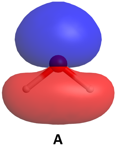
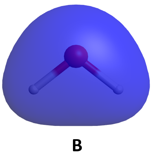
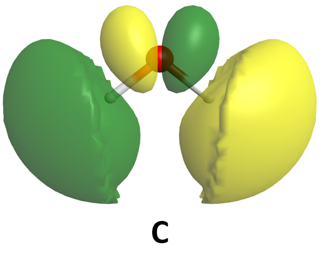
Some of the molecular orbitals for a water molecule are shown here. Based only on what you know about the appearance of bonding and antibonding orbitals, rank these MOs from lowest-energy to highest-energy. (Click on each image for a rotatable 3D view of the MO.)
D6.4 Lewis Structures for Covalent Molecules
Molecular orbitals for molecules with three or more atoms are complicated and hard to draw. Thus, although MOs would convey a more descriptive and accurate picture of electron distribution within a molecule, chemists often rely on simpler diagrams to depict the covalent bonding. It will aid your understanding of chemistry if you can connect these simpler diagrams mentally with the more complete picture given by MOs.
The most commonly used hand-drawn depiction is the Lewis structure: a diagram that represents atomic nuclei and core electrons by chemical symbols and valence electrons as dots or lines. A Lewis structure is built by combining Lewis diagrams (Section D3.4) of the constituent atoms.
Activity 2: Lewis Diagrams
Consider each element listed below. In your course notebook write the electron configuration for an atom of each element, determine the number of valence electrons, and write a Lewis diagram (Section D3.4). How are the Lewis diagrams related to the position of each element in the periodic table?
N C S As O Br F Si H
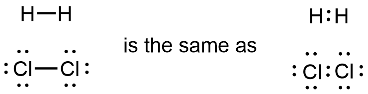
In Lewis structures, a single covalent bond is drawn as a pair of electron dots shared between two adjacent atoms, a bond pair. Valence electrons that are not in a bond are shown as pairs of dots associated with individual atoms, lone pairs. For example:
![]()
In the Cl2 molecule, each Cl atom has three lone pairs and the two Cl atoms share one bond pair. Hence, each Cl atom in Cl2 has formed an octet (is surrounded by eight valence electrons).
For simplicity and clarity, a bond pair is typically represented by a line instead of a pair of dots:
Activity 3: Lewis Structure and Electron Sharing
The Octet Rule
The octet rule states that atoms of main-group elements tend to gain, lose, or share enough electrons to form an octet (eight valence electrons). Such noble-gas electron configurations with completely filled valence shells are more stable, and therefore should correspond to how the electrons are arranged in a molecule.
The Lewis diagram for an atom can be used to predict the number of bonds the atom will form. For example, a carbon atom has four valence electrons and therefore requires four more electrons to reach an octet:
It is important to keep in mind that it is impossible to exceed an octet for atoms in the second period. This is particularly relevant because you will encounter numerous molecules containing the elements C, N and O.
Finally, because a hydrogen atom needs only two electrons to fill its valence shell, H is an important exception to the octet rule and forms only one bond.
Exercise 7: Number of Bonds
Double and Triple Bonds
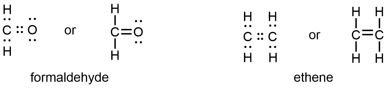
Two atoms may need to share more than one pair of electrons to achieve the requisite octet. In other words, the bond order is greater than 1. A double bond consists of two pairs of electrons being shared between two atoms. For example:
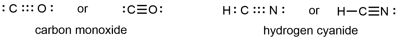
A triple bond forms when three pairs of electron are shared between two atoms. For example:
Activity 4: Double and Triple Bonds
Write answers to these questions in your course notebook:
Write a Lewis structure for N2 and a Lewis structure for O2. Describe the type of bond in each case.
Do the N atoms in N2 and the O atoms in O2 follow the rule for number of bonds in Exercise 7?
Use the molecular-orbital energy level diagram in Figure 1 to calculate the bond order for N2 and for O2. How do the bond orders relate to the Lewis structures?
D6.5 General Guidance for Drawing Lewis Structures
Often you can draw a Lewis structure based on the number of bonds formed by each kind of atom. in more complicated cases, here is a step-by-step procedure for drawing Lewis structures of molecules and polyatomic ions:
- Determine the total number of valence electrons by summing the number of valence electrons on all atoms.
- For a polyatomic cation, subtract one electron for each positive charge.
- For a polyatomic anion, add one electron for each negative charge.
- Choose one or more central atoms; a central atom bonds to several other atoms and is usually the atom that forms the greatest number of bonds.
- Usually the central atom is written first in a chemical formula, such as P in PCl3.
- If there are two or more central atoms, connect them using single bond lines.
- Draw a skeleton structure of the molecule by arranging the other atoms (which are called terminal atoms) around the central atom or atoms.
- Connect terminal atoms to the central atom(s) by single bond lines.
- Distribute the remaining electrons as lone pairs on the terminal atoms (except hydrogen), completing an octet around each atom.
- If there are still valence electrons available, place them on the central atom(s).
- If the number of electrons around a central atom is less than an octet, rearrange the electrons to make multiple bonds with the central atom(s) until each atom has an octet.
Let’s apply these rules to a simple molecule, ammonia, NH3.
Here is a more complicated case: ethene (ethylene), C2H4.
Exercise 8: Lewis Structures and Valence Electrons
If you were to build a Lewis structure for nitrate ion (NO3‾), how many electrons would you need to allocate in your structure? (In other words, how many non-core electrons have to be in your structure?)
Exercise 9: Identifying Incorrect Lewis Structures
For each Lewis structure, determine whether the structure is correct. If the structure is incorrect, identify the error made in the representation.
D6.6 Exceptions to the Octet Rule
Some stable covalent molecules contain one or more atoms that do not have an octet. Such molecules fall into three categories.
Odd-electron Molecules
A molecule that contains an odd number of electrons must have at least one electron unpaired and therefore must have an atom with fewer than eight electrons in its valence shell (typically it’s seven electrons). A molecule with at least one unpaired electron is called a free radical. Nitric oxide, NO, which is produced in internal combustion engines when oxygen and nitrogen react at high temperatures, is an example.
To draw the Lewis structure for an odd-electron molecule, follow the same steps as outlined previously, but recognize that an odd-electron molecule must have less than an octet on some atom. For example, the Lewis structure for NO is:
![]()
Forming a triple bond would cause either oxygen or nitrogen to exceed an octet, which is a very unlikely electron arrangement.
Molecules with an Incomplete Octet on a Central Atom
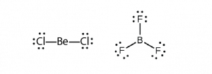
Some molecules contain a central atom that does not have a filled valence shell. Usually, these central atoms are from groups 2 (IIA) and 13 (IIIA). For example, the Lewis structure of beryllium chloride, BeCl2, shows beryllium with only four electrons, and that of boron trifluoride, BF3, shows boron with only six electrons.
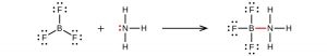
It is possible to draw a structure for each of these molecules where there are double bonds to the central atom and therefore an octet. For example, BF3 with one B=F double bond would satisfy the octet rule. However, experimental evidence tells us that the bond lengths in BF3 are closer to B–F single bonds. The observed reactivity of BF3 is also consistent with less than an octet on boron: BF3 reacts readily with NH3, with the lone pair on nitrogen (red) forming a bond (red) that completes the octet on the boron atom:
Molecules with More Than an Octet on a Central Atom
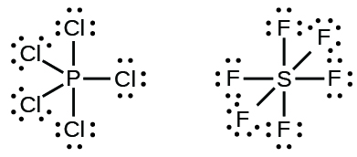
Some Lewis structures show more than four pairs of electrons around the central atom. This usually happens when the central atom is in the third or a higher period (n ≥ 3). Molecules with more than an octet around a central atom are called hypervalent molecules. For example, in the Lewis structure for PCl5, the central phosphorus atom is surrounded by five pairs of electrons. In SF6, sulfur has six pairs of electrons.
Exercise 10: Exceptions to the Octet Rule
Day 6 Pre-class Podia Problem: Molecular Orbital Energy Levels
This Podia problem is based on today’s pre-class material; working through that material will help you solve the problem.
The molecule C2 is quite unstable and can only be isolated and studied experimentally in the gas phase. Molecular spectroscopy of C2 reveals that a C2 molecule in the ground state has no unpaired electrons.
- Use the MO energy-level diagram in Figure 1 to predict the ground state electron configuration of C2. Does your result agree with the experimental observation?
- Consider the MO diagram below. Is this a better diagram than Figure 1 for C2? Use scientifically appropriate language to explain which diagram is better.
Two days before the next whole-class session, this Podia question will become live on Podia, where you can submit your answer.
