Additional Reading Materials

Chapter 17: Electrochemistry

Ch17.1 Electrochemistry

Electrochemistry deals with chemical reactions that produce electricity and the changes associated with the passage of electrical current through matter. The reactions involve electron transfer, and so they are oxidation-reduction (or redox) reactions. Many metals may be purified or electroplated using electrochemical methods. Devices such as automobiles, smartphones, electronic tablets, watches, pacemakers, and many others use batteries for power. Batteries use chemical reactions that produce electricity spontaneously and that can be converted into useful work. All electrochemical systems involve the transfer of electrons in a reacting system. In many systems, the reactions occur in a region known as the cell, where the transfer of electrons occurs at electrodes.

Electricity refers to a number of phenomena associated with the presence and flow of electric charge. Electricity includes such diverse things as lightning, static electricity, the current generated by a battery as it discharges, and many other influences on our daily lives. The flow or movement of charge is an electric current (Figure 1). Electrons or ions may carry the charge. The elementary unit of charge is the charge of an electron, which is 1.602 × 10⁻¹⁹ C (the SI unit is the coulomb). The presence of an electric charge generates an electric field. Electric current is the rate of flow of charge, and has the SI unit called the ampere (A), which is a flow rate of 1 coulomb of charge per second (1 A = 1 C/s). An electric current flows in a path, called an electric circuit. In most chemical systems, it is necessary to maintain a closed path for current to flow. The flow of charge is generated by an electrical potential difference, or potential, between two points in the circuit. Electrical potential is the ability of the electric field to do work on the charge. The SI unit of electrical potential is the volt (V). When 1 coulomb of charge moves through a potential difference of 1 volt, it gains or loses 1 joule (J) of energy. Table 1 summarizes some of this information about electricity.

Quantity Definition Measure or Unit
Electric charge Charge of an electron 1.602 × 10⁻¹⁹ C
Electric current The movement of charge ampere = A = 1 C/s
Electric potential work needed to move the charge volt = V = J/C
Electric field The force acting upon other charges in the vicinity
Table 1. Common Electrical Terms
Three photographs are shown in this figure. The first shows lightning against a dark evening sky. The second shows a child at the open base of a green plastic playground tube slide. The child’s hair is sticking up and the child’s shadow on the base of the slide shows the child’s hair sticking up and out in all directions. The final picture shows a 9 volt battery from which red and blue coated wire that is twisted together extend from the battery terminals to the lower region of a yellow platform or board. Above this region are six resistors in a horizontal row, evenly spaced horizontally across the span of the board. Green, blue, and white wires are also visible on the board. 6 orange L E D light bulbs extend from the upper edge of the platform in a horizontal line parallel to the pegs.
Figure 1. Electricity-related phenomena include lightning, accumulation of static electricity, and current produced by a battery. (credit left: modification of work by Thomas Bresson; credit middle: modification of work by Chris Darling; credit right: modification of work by Windell Oskay)

Ch17.2 Redox Reactions and Oxidation Number

The term oxidation was originally used to describe chemical reactions involving O2, but its meaning has evolved to refer to a broad and important reaction class known as oxidation-reduction (redox) reactions.

Some redox reactions involve the transfer of electrons between reactant species to yield ionic products, such as the reaction between sodium and chlorine to yield sodium chloride:

[latex]2\text{Na}(s) + \text{Cl}_2(g) \longrightarrow 2\text{NaCl}(s)[/latex]

It is helpful to view the process with regard to each individual reactant, that is, to represent the fate of each reactant in the form of an equation called a half-reaction:

[latex]2\text{Na}(s) \longrightarrow 2\text{Na}^{+}(s) + 2\text{e}^{-}[/latex]
[latex]\text{Cl}_2(g) + 2\text{e}^{-} \longrightarrow 2\text{Cl}^{-}(s)[/latex]

These equations show that Na atoms lose electrons while Cl atoms (in the Cl2 molecule) gain electrons. For redox reactions of this sort, the loss and gain of electrons define the complementary processes that occur:

[latex]\begin{array}{rcl} \pmb{\text{oxidation}} &=& \text{loss of electrons} \\[1em] \pmb{\text{reduction}} &=& \text{gain of electrons} \end{array}[/latex]

In this reaction, then, sodium is oxidized and chlorine undergoes reduction. Viewed from a more active perspective, sodium functions as a reducing agent (reductant), since it provides electrons to (or reduces) chlorine. Likewise, chlorine functions as an oxidizing agent (oxidant), as it effectively removes electrons from (oxidizes) sodium.

[latex]\begin{array}{rcl} \pmb{\text{reducing agent}} &=& \text{species that is oxidized} \\[1em] \pmb{\text{oxidizing agent}} &=& \text{species that is reduced} \end{array}[/latex]

Some redox processes, however, do not involve the transfer of electrons. Consider, for example, a reaction similar to the one yielding NaCl:

[latex]\text{H}_2(g) + \text{Cl}_2(g) \longrightarrow 2 \text{HCl}(g)[/latex]
The product of this reaction is a covalent compound, so transfer of electrons in the explicit sense is not involved. To clarify the similarity of this reaction to the previous one and permit an unambiguous definition of redox reactions, a property called oxidation number has been defined. The oxidation number (or oxidation state) of an element in a compound is the charge its atoms would possess if the compound was ionic. The following guidelines are used to assign oxidation numbers to each element in a molecule or ion.
  1. The oxidation number of an atom in an elemental substance is zero.
  2. The oxidation number of a monatomic ion is equal to the ion’s charge.
  3. Oxidation numbers for common nonmetals are usually assigned as follows:
    • Hydrogen: +1 when combined with nonmetals, −1 when combined with metals
    • Oxygen: −2 in most compounds, sometimes −1 (so-called peroxides, O22−), very rarely [latex]-\frac{1}{2}[/latex] (so-called superoxides, O2), positive values when combined with F (values vary)
    • Halogens: −1 for F always, −1 for other halogens except when combined with oxygen or more electronegative halogens (positive oxidation numbers in these cases, varying values)
  4. The sum of oxidation numbers for all atoms in a molecule or polyatomic ion equals the charge on the molecule or ion.

Example 1

Assigning Oxidation Numbers
Follow the guidelines above to assign oxidation numbers to all the elements in the following species:

(a) H2S

(b) SO32−

(c) Na2SO4

Solution
(a) According to guideline 3, the oxidation number for H is +1.

Using this oxidation number and the compound’s formula, guideline 4 may then be used to calculate the oxidation number for sulfur:

[latex]\text{charge on H}_2 \text{S} = 0 = (2 \times (+1)) + (1 \times x)[/latex]
[latex]x = -2[/latex]

(b) Guideline 3 suggests the oxidation number for oxygen is −2.

Using this oxidation number and the ion’s formula, guideline 4 may then be used to calculate the oxidation number for sulfur:

[latex]{\text{charge on SO}_3}^{2-} = -2 = (3 \times (-2)) + (1 \times x)[/latex]
[latex]x = +4[/latex]

(c) For ionic compounds, it’s convenient to assign oxidation numbers for the cation and anion separately.

According to guideline 2, the oxidation number for sodium is +1.

Assuming the usual oxidation number for oxygen (-2 per guideline 3), the oxidation number for sulfur is calculated as directed by guideline 4:

[latex]{\text{charge on SO}_4}^{2-} = -2 = (4 \times (-2)) + (1 \times x)[/latex]
[latex]x = +6[/latex]

Check Your Learning
Assign oxidation states to the elements whose atoms are underlined in each of the following compounds or ions:

(a) KNO3

(b) AlH3

(c) NH4+

(d) H2PO4

Answer:

(a) N, +5; (b) Al, +3; (c) N, −3; (d) P, +5

Using the oxidation number concept, an all-inclusive definition of redox reaction has been established. Oxidation-reduction (redox) reactions are those in which one or more elements involved undergo a change in oxidation number. (While the vast majority of redox reactions involve changes in oxidation number for two or more elements, a few interesting exceptions to this rule do exist, see Example 2.) Definitions for the complementary processes of this reaction class are correspondingly revised as shown here:

[latex]\pmb{\text{oxidation}} = \text{increase in oxidation number}[/latex]
[latex]\pmb{\text{reduction}} = \text{decrease in oxidation number}[/latex]

In the reaction between sodium and chlorine to yield sodium chloride, sodium is oxidized (its oxidation number increases from 0 in Na to +1 in NaCl) and chlorine is reduced (its oxidation number decreases from 0 in Cl2 to −1 in NaCl). In the reaction between molecular hydrogen and chlorine, hydrogen is oxidized (its oxidation number increases from 0 in H2 to +1 in HCl) and chlorine is reduced (its oxidation number decreases from 0 in Cl2 to −1 in HCl).

Several subclasses of redox reactions are recognized, including combustion reactions in which the reductant (also called a fuel) and oxidant (often, but not necessarily, molecular oxygen) react vigorously and produce significant amounts of heat, and often light, in the form of a flame. A typical propellant reaction in which solid aluminum is oxidized by ammonium perchlorate is represented by this equation:

[latex]10\text{Al}(s) + 6\text{NH}_4 \text{ClO}_4(s) \longrightarrow 4\text{Al}_2 \text{O}_3(s) + 2\text{AlCl}_3(s) + 12\text{H}_2 \text{O}(g) + 3\text{N}_2(g)[/latex]

Watch a brief video showing the test firing of a small-scale, prototype, hybrid rocket engine planned for use in the new Space Launch System being developed by NASA. The first engines firing at 3 s (green flame) use a liquid fuel/oxidant mixture, and the second, more powerful engines firing at 4 s (yellow flame) use a solid mixture.

Single-displacement (replacement) reactions are redox reactions in which an ion in solution is displaced (or replaced) via the oxidation of a metallic element. One common example of this type of reaction is the acid oxidation of certain metals:

[latex]\text{Zn}(s) + 2\text{HCl}(aq) \longrightarrow \text{ZnCl}_2(aq) + \text{H}_2(g)[/latex]

Metallic elements may also be oxidized by solutions of other metal salts; for example:

[latex]\text{Cu}(s) + 2 \text{AgNO}_3(aq) \longrightarrow \text{Cu(NO}_3)_2(aq) + 2 \text{Ag}(s)[/latex]

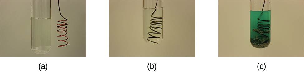
This reaction may be observed by placing copper wire in a solution containing a dissolved silver salt. Silver ions in solution are reduced to elemental silver at the surface of the copper wire, and the resulting Cu2+ ions dissolve in the solution to yield a characteristic blue color (Figure 2).

This figure contains three photographs. In a, a coiled copper wire is shown beside a test tube filled with a clear, colorless liquid. In b, the wire has been inserted into the test tube with the clear, colorless liquid. In c, the test tube contains a light blue liquid and the coiled wire appears to have a fuzzy silver gray coating.
Figure 2. (a) A copper wire is shown next to a solution containing silver(I) ions. (b) Displacement of dissolved silver ions by copper ions results in (c) accumulation of gray-colored silver metal on the wire and development of a blue color in the solution, due to dissolved copper ions. (credit: modification of work by Mark Ott)

Example 2

Describing Redox Reactions
Identify which equations represent redox reactions. For those reactions identified as redox, name the oxidant and reductant.

(a) [latex]\text{ZnCO}_3(s) \longrightarrow \text{ZnO}(s) + \text{CO}_2(g)[/latex]

(b) [latex]2\text{Ga}(l) + 3\text{Br}_2(l) \longrightarrow 2\text{GaBr}_3(s)[/latex]

(c) [latex]2\text{H}_2 \text{O}_2(aq) \longrightarrow 2\text{H}_2 \text{O}(l) + \text{O}_2(g)[/latex]

(d) [latex]\text{BaCl}_2(aq) + \text{K}_2 \text{SO}_4(aq) \longrightarrow \text{BaSO}_4(s) + 2\text{KCl}(aq)[/latex]

(e) [latex]\text{C}_2 \text{H}_4(g) + 3\text{O}_2(g) \longrightarrow 2\text{CO}_2(g) + 2\text{H}_2 \text{O}(l)[/latex]

Solution
Redox reactions are identified if one or more elements undergo a change in oxidation number.

(a) This is not a redox reaction, since oxidation numbers remain unchanged for all elements.

(b) This is a redox reaction. Gallium is oxidized, its oxidation number increasing from 0 in Ga(l) to +3 in GaBr3(s). The reducing agent is Ga(l). Bromine is reduced, its oxidation number decreasing from 0 in Br2(l) to −1 in GaBr3(s). The oxidizing agent is Br2(l).

(c) This is a redox reaction. It is a particularly interesting process, as it involves the same element, oxygen, undergoing both oxidation and reduction (a so-called disproportionation reaction). Oxygen is oxidized, its oxidation number increasing from −1 in H2O2(aq) to 0 in O2(g). Oxygen is also reduced, its oxidation number decreasing from −1 in H2O2(aq) to −2 in H2O(l). For disproportionation reactions, the same substance functions as an oxidant and a reductant.

(d) This is not a redox reaction, since oxidation numbers remain unchanged for all elements.

(e) This is a redox reaction (combustion). Carbon is oxidized, its oxidation number increasing from −2 in C2H4(g) to +4 in CO2(g). The reducing agent (fuel) is C2H4(g). Oxygen is reduced, its oxidation number decreasing from 0 in O2(g) to −2 in H2O(l). The oxidizing agent is O2(g).

Check Your Learning
This equation describes the production of tin(II) chloride:

[latex]\text{Sn}(s) + 2\text{HCl}(g) \longrightarrow \text{SnCl}_2(s) + \text{H}_2(g)[/latex]

Is this a redox reaction? If so, identify the oxidant and reductant.

Answer:

Yes, it is a single-replacement reaction. Sn(s) is the reductant, HCl(g) is the oxidant.

Ch17.3 Balancing Redox Reactions

We will concentrate on the half-reaction method for balancing redox reactions. The use of half-reactions is important partly for balancing more complicated reactions and partly because many aspects of electrochemistry are easier to discuss in terms of half-reactions. There are alternate methods of balancing these reactions; however, there are no good alternatives to half-reactions for discussing what is occurring in many systems. The half-reaction method splits oxidation-reduction reactions into their oxidation “half” and reduction “half” to make finding the overall equation easier.

Electrochemical reactions frequently occur in solutions, which can be acidic, basic, or neutral. When balancing oxidation-reduction reactions, the nature of the solution may be important. It helps to see this in an actual problem. Consider the following unbalanced oxidation-reduction reaction in acidic solution:

[latex]\text{MnO}_4^{\;\;-}(aq)\;+\;\text{Fe}^{2+}(aq)\;{\longrightarrow}\;\text{Mn}^{2+}(aq)\;+\;\text{Fe}^{3+}(aq)[/latex]

We can start by collecting the species we have so far into an unbalanced oxidation half-reaction and an unbalanced reduction half-reaction. Each of these half-reactions contain the same element in two different oxidation states. The Fe2+ has lost an electron to become Fe3+; therefore, the iron underwent oxidation. The manganese underwent reduction; it gained five electrons to change from Mn7+ to Mn2+.

[latex]\begin{array}{lrcl} \text{oxidation (unbalanced):} & \text{Fe}^{2+}(aq) &\longrightarrow& \text{Fe}^{3+}(aq) \\[0.5em] \text{reduction (unbalanced):} & \text{MnO}_4^{\;\;-}(aq) &\longrightarrow& \text{Mn}^{2+}(aq) \end{array}[/latex]

In Acidic Solution

In acidic solution, there are H+ ions present, which are often useful in balancing half-reactions where the reactants or products contain hydrogen and/or oxygen. It may be necessary to use H+ directly or as a reactant that may react with oxygen to generate water. In this example, the oxidation half-reaction involves neither hydrogen nor oxygen, so hydrogen ions are not necessary to the balancing. However, the reduction half-reaction does involve oxygen. It is necessary to use H+ to convert this oxygen to water.

[latex]\text{charge not balanced: MnO}_4^{\;\;-}(aq)\;+\;8\text{H}^{+}(aq)\;{\longrightarrow}\;\text{Mn}^{2+}(aq)\;+\;4\text{H}_2\text{O}(l)[/latex]

The iron atoms in the oxidation half-reaction are balanced (mass balance); however, the charge is unbalanced since the charges on the ions are not equal. It is necessary to use electrons to balance the charge. The way to balance the charge is by adding electrons to one side of the equation. Adding a single electron on the right side gives a balanced oxidation half-reaction:

[latex]\text{oxidation (balanced): Fe}^{2+}(aq)\;{\longrightarrow}\;\text{Fe}^{3+}(aq)\;+\;\text{e}^{-}[/latex]

You should check the half-reaction for the number of each atom type and the total charge on each side of the equation. The charges include the actual charges of the ions times the number of ions and the charge on an electron times the number of electrons.

[latex]\text{Fe: Does}\;(1\;\times\;1) = (1\;\times\;1)\text{? Yes.} \\[0.5em] \text{Charge: Does}\;[1\;\times\;(+2)] = [1\;\times\;(+3)\;+\;1\;\times\;(-1)]\text{? Yes.}[/latex]

If the atoms and charges balance, the half-reaction is balanced. In oxidation half-reactions, electrons appear as products (on the right). Since iron underwent oxidation, iron is the reducing agent.

Now return to the reduction half-reaction equation:

[latex]\text{reduction (unbalanced): MnO}_4^{\;\;-}(aq)\;+\;8\text{H}^{+}(aq)\;{\longrightarrow}\;\text{Mn}^{2+}(aq)\;+\;4\text{H}_2\text{O}(l)[/latex]

The atoms are balanced (mass balance), so it is now necessary to check for charge balance. The total charge on the left of the reaction arrow is [(−1) × (1) + (8) × (+1)] = +7, while the total charge on the right side is [(1) × (+2) + (4) × (0)] = +2. The difference between +7 and +2 is five; therefore, it is necessary to add five electrons to the left side to achieve charge balance.

[latex]\text{Reduction (balanced): MnO}_4^{\;\;-}(aq)\;+\;8\text{H}^{+}(aq)\;+\;5\text{e}^{-}\;{\longrightarrow}\;\text{Mn}^{2+}(aq)\;+\;4\text{H}_2\text{O}(l)[/latex]

You should check this half-reaction for each atom type and for the charge:

[latex]\text{Mn: Does}\;(1\;\times\;1) = (1\;\times\;1)\text{? Yes.} \\[0.5em] \text{H: Does}\;(8\;\times\;1) = (4\;\times\;2)\text{? Yes.} \\[0.5em] \text{O: Does}\;(1\;\times\;4) = (4\;\times\;1)\text{? Yes.} \\[0.5em] \text{Charge: Does}\;[1\;\times\;(-1)\;+\;8\;\times\;(+1)\;+\;5\;\times\;(-1)] = [1\;\times\;(+2)]\text{? Yes.}[/latex]

Now that this half-reaction is balanced, it is easy to see it involves reduction because electrons were gained when MnO4 was reduced to Mn2+. In all reduction half-reactions, electrons appear as reactants (on the left side). The species that was reduced, MnO4, is the oxidizing agent.

We now have two balanced half-reactions.

[latex]\begin{array}{lrcl} \text{oxidation:} & \text{Fe}^{2+}(aq) &\longrightarrow& \text{Fe}^{3+}(aq)\;+\;\text{e}^{-} \\[0.5em] \text{reduction:} & \text{MnO}_4^{\;\;-}(aq)\;+\;8\text{H}^{+}(aq)\;+\;5\text{e}^{-} &\longrightarrow& \text{Mn}^{2+}(aq)\;+\;4\text{H}_2\text{O}(l) \end{array}[/latex]

It is now necessary to combine the two halves to produce a whole reaction. The key to combining the half-reactions is the electrons. The electrons lost during oxidation go to cause reduction. The number of electrons transferred from the oxidation half-reaction to the reduction half-reaction must be equal. There can be no missing or excess electrons. In this example, the oxidation half-reaction generates one electron, while the reduction half-reaction requires five. The lowest common multiple of one and five is five; therefore, it is necessary to multiply every term in the oxidation half-reaction by five and every term in the reduction half-reaction by one. (In this case, the multiplication of the reduction half-reaction generates no change; however, this will not always be the case.) The multiplication of the two half-reactions by the appropriate factor followed by addition of the two halves gives:

[latex]\begin{array}{lrcl} \text{oxidation:} & 5\;\times\;(\text{Fe}^{2+}(aq) &\longrightarrow& \text{Fe}^{3+}(aq)\;+\;\text{e}^{-}) \\[0.5em] \text{reduction:} & \text{MnO}_4^{\;\;-}(aq)\;+\;8\text{H}^{+}(aq)\;+\;5\text{e}^{-} &\longrightarrow& \text{Mn}^{2+}(aq)\;+\;4\text{H}_2\text{O}(l) \\[0.5em] \hline \\[0.5em] \text{overall:} & 5\text{Fe}^{2+}(aq)\;+\;\text{MnO}_4^{\;\;-}(aq)\;+\;8\text{H}^{+}(aq) &\longrightarrow& 5\text{Fe}^{3+}(aq)\;+\;\text{Mn}^{2+}(aq)\;+\;4\text{H}_2\text{O}(l) \end{array}[/latex]

The electrons do not appear in the final answer because the oxidation electrons are the same electrons as the reduction electrons and they “cancel.” Carefully check each side of the overall equation to verify everything was combined correctly:

[latex]\text{Fe: Does}\;(5\;\times\;1) = (5\;\times\;1)\text{? Yes.} \\[0.5em] \text{Mn: Does}\;(1\;\times\;1) = (1\;\times\;1)\text{? Yes.} \\[0.5em] \text{H: Does}\;(8\;\times\;1) = (4\;\times\;2)\text{? Yes.} \\[0.5em] \text{O: Does}\;(1\;\times\;4) = (4\;\times\;1)\text{? Yes.} \\[0.5em] \text{Charge: Does}\;[5\;\times\;(+2)\;+\;1\;\times\;(-1)\;+\;8\;\times\;(+1)] = [5\;\times\;(+3)\;+\;1\;\times\;(+2)]\text{? Yes.}[/latex]

Everything checks, so this is the overall equation in acidic solution. If something does not check, the most common error occurs during the multiplication of the individual half-reactions.

Example 3

Balancing Acidic Oxidation-Reduction Reactions
Balance the following reaction in acidic solution:

[latex]\text{MnO}_4^{\;\;-}(aq)\;+\;\text{Cr}^{3+}(aq)\;{\longrightarrow}\;\text{Mn}^{2+}(aq)\;+\;\text{Cr}_2\text{O}_7^{\;\;2-}(aq)[/latex]

Solution
This is an oxidation-reduction reaction, so start by collecting the species given into an unbalanced oxidation half-reaction and an unbalanced reduction half-reaction.

[latex]\begin{array}{lrcl} \text{oxidation (unbalanced):} & \text{Cr}^{3+}(aq) &\longrightarrow& \text{Cr}_2\text{O}_7^{\;\;2-}(aq) \\[0.5em] \text{reduction (unbalanced):} & \text{MnO}_4^{\;\;-}(aq) &\longrightarrow& \text{Mn}^{2+}(aq) \end{array}[/latex]

Starting with the oxidation half-reaction, we can balance the chromium

[latex]\text{oxidation (unbalanced):}\;2\text{Cr}^{3+}(aq)\;{\longrightarrow}\;\text{Cr}_2\text{O}_7^{\;\;2-}(aq)[/latex]

In acidic solution, we can use H+. Adding seven water molecules to the left side provides the necessary oxygen; the “left over” hydrogen appears as 14 H+ on the right:

[latex]\text{oxidation (unbalanced):}\;2\text{Cr}^{3+}(aq)\;+\;7\text{H}_2\text{O}(l)\;{\longrightarrow}\;\text{Cr}_2\text{O}_7^{\;\;2-}(aq)\;+\;14\text{H}^{+}(aq)[/latex]

The left side of the equation has a total charge of [2 × (+3) = +6], and the right side a total charge of [−2 + 14 × (+1) = +12]. The difference is six; adding six electrons to the right side produces a mass- and charge-balanced oxidation half-reaction (in acidic solution):

[latex]\text{oxidation (balanced):}\;2\text{Cr}^{3+}(aq)\;+\;7\text{H}_2\text{O}(l)\;{\longrightarrow}\;\text{Cr}_2\text{O}_7^{\;\;2-}(aq)\;+\;14\text{H}^{+}(aq)\;+\;6\text{e}^{-}[/latex]

Checking the half-reaction:

[latex]\text{Cr: Does}\;(2\;\times\;1) = (1\;\times\;2)\text{? Yes.} \\[0.5em] \text{H: Does}\;(7\;\times\;2) = (14\;\times\;1)\text{? Yes.} \\[0.5em] \text{O: Does}\;(7\;\times\;1) = (1\;\times\;7)\text{? Yes.} \\[0.5em] \text{Charge: Does}\;[2\;\times\;(+3)] = [1\;\times\;(-2)\;+\;14\;\times\;(+1)\;+\;6\;\times\;(-1)]\text{? Yes.}[/latex]

Now work on the reduction. It is necessary to convert the four oxygen atoms in the permanganate into four water molecules. To do this, add eight H+ to convert the oxygen into four water molecules:

[latex]\text{reduction (unbalanced): MnO}_4^{\;\;-}(aq)\;+\;8\text{H}^{+}(aq)\;{\longrightarrow}\;\text{Mn}^{2+}(aq)\;+\;4\text{H}_2\text{O}(l)[/latex]

Then add five electrons to the left side to balance the charge:

[latex]\text{reduction (balanced): MnO}_4^{\;\;-}(aq)\;+\;8\text{H}^{+}(aq)\;+\;5\text{e}^{-}\;{\longrightarrow}\;\text{Mn}^{2+}(aq)\;+\;4\text{H}_2\text{O}(l)[/latex]

Make sure to check the half-reaction:

[latex]\text{Mn: Does}\;(1\;\times\;1) = (1\;\times\;1)\text{? Yes.} \\[0.5em] \text{H: Does}\;(8\;\times\;1) = (4\;\times\;2)\text{? Yes.} \\[0.5em] \text{O: Does}\;(1\;\times\;4) = (4\;\times\;1)\text{? Yes.} \\[0.5em] \text{Charge: Does}\;[1\;\times\;(-1)\;+\;8\;\times\;(+1)\;+\;5\;\times\;(-1)] = [1\;\times\;(+2)]\;\text{? Yes.}[/latex]

Collecting what we have so far:

[latex]\begin{array}{lrcl} \text{oxidation:} & 2\text{Cr}^{3+}(aq)\;+\;7\text{H}_2\text{O}(l) &\longrightarrow& \text{Cr}_2\text{O}_7^{\;\;2-}(aq)\;+\;14\text{H}^{+}(aq)\;+\;6\text{e}^{-} \\[0.5em] \text{reduction:} & \text{MnO}_4^{\;\;-}(aq)\;+\;8\text{H}^{+}(aq)\;+\;5\text{e}^{-} &\longrightarrow& \text{Mn}^{2+}(aq)\;+\;4\text{H}_2\text{O}(l) \end{array}[/latex]

The least common multiple for the electrons is 30, so multiply the oxidation half-reaction by five, the reduction half-reaction by six, combine, and simplify:

[latex]10\text{Cr}^{3+}(aq)\;+\;35\text{H}_2\text{O}(l)\;+\;6\text{MnO}_4^{\;\;-}(aq)\;+\;48\text{H}^{+}(aq)\;{\longrightarrow}\;5\text{Cr}_2\text{O}_7^{\;\;2-}(aq)\;+\;70\text{H}^{+}(aq)\;+\;6\text{Mn}^{2+}(aq)\;+\;24\text{H}_2\text{O}(l)[/latex]
[latex]10\text{Cr}^{3+}(aq)\;+\;11\text{H}_2\text{O}(l)\;+\;6\text{MnO}_4^{\;\;-}(aq)\;{\longrightarrow}\;5\text{Cr}_2\text{O}_7^{\;\;2-}(aq)\;+\;22\text{H}^{+}(aq)\;+\;6\text{Mn}^{2+}(aq)[/latex]

Checking each side of the equation:

[latex]\text{Mn: Does}\;(6\;\times\;1) = (6\;\times\;1)\text{? Yes.} \\[0.5em] \text{Cr: Does}(10\;\times\;1) = (5\;\times\;2)\text{? Yes.} \\[0.5em] \text{H: Does}\;(11\;\times\;2) = (22\;\times\;1)\text{? Yes.} \\[0.5em] \text{O: Does}\;(11\;\times\;1\;+\;6\;\times\;4) = (5\;\times\;7)\text{? Yes.} \\[0.5em] \text{Charge: Does}\;[10\;\times\;(+3)\;+\;6\;\times\;(-1)] = [5\;\times\;(-2)\;+\;22\;\times\;(+1)\;+\;6\;\times\;(+2)]\text{? Yes.}[/latex]

This is the balanced equation in acidic solution.

Check your learning
Balance the following equation in acidic solution:

[latex]\text{Hg}_2^{\;\;2+}(aq)\;+\;\text{Ag}(s)\;{\longrightarrow}\;\text{Hg}(l)\;+\;\text{Ag}^{+}(aq)[/latex]

Answer:

[latex]\text{Hg}_2^{\;\;2+}(aq)\;+\;2\text{Ag}(s)\;{\longrightarrow}\;2\text{Hg}(l)\;+\;2\text{Ag}^{+}(aq)[/latex]

In Basic Solution

The situation is different in basic solution because the basic solutions have excess OH ions. (A neutral solution may be treated as acidic or basic, though treating it as acidic is usually easier.) Some of these hydroxide ions will react with H+ to produce water. The simplest way to generate the balanced overall equation in basic solution is to start with the balanced equation in acidic solution, then “convert” it to the equation for basic solution. However, it is necessary to exercise caution when doing this, as many reactants behave differently under basic conditions and many metal ions will precipitate as the metal hydroxide. We just produced the following reaction, which we want to change to a basic reaction:

[latex]5\text{Fe}^{2+}(aq)\;+\;\text{MnO}_4^{\;\;-}(aq)\;+\;8\text{H}^{+}(aq)\;{\longrightarrow}\;5\text{Fe}^{3+}(aq)\;+\;\text{Mn}^{2+}(aq)\;+\;4\text{H}_2\text{O}(l)[/latex]

However, under basic conditions, MnO4 normally reduces to MnO2 and iron will be present as either Fe(OH)2 or Fe(OH)3. For these reasons, under basic conditions, this reaction will be

[latex]3\text{Fe(OH)}_2(s)\;+\;\text{MnO}_4^{\;\;-}(aq)\;+\;2\text{H}_2\text{O}(l)\;{\longrightarrow}\;3\text{Fe(OH)}_3(s)\;+\;\text{MnO}_2(s)\;+\;\text{OH}^{-}(aq)[/latex]

(Under very basic conditions MnO4 will reduce to MnO42-, instead of MnO2.)

It is still possible to balance any oxidation-reduction reaction as an acidic reaction and then, when necessary, convert the equation to a basic reaction. This will work if the acidic and basic reactants and products are the same or if the basic reactants and products are used before the conversion from acidic or basic. To convert to a basic reaction, it is necessary to add the same number of OH to each side of the equation so that all the H+ are removed and mass balance is maintained. H+ combines with OH to produce water.

Let us now try a basic equation. We will start with the following basic reaction:

[latex]\text{Cl}^{-}(aq)\;+\;\text{MnO}_4^{\;\;-}(aq)\;{\longrightarrow}\;\text{ClO}_3^{\;\;-}(aq)\;+\;\text{MnO}_2(s)[/latex]

Balancing this as acid gives

[latex]\text{Cl}^{-}(aq)\;+\;2\text{MnO}_4^{\;\;-}(aq)\;+\;2\text{H}^{+}(aq)\;{\longrightarrow}\;\text{ClO}_3^{\;\;-}(aq)\;+\;2\text{MnO}_2(s)\;+\;\text{H}_2\text{O}(l)[/latex]

In this case, it is necessary to add two hydroxide ions to each side of the equation to convert the two hydrogen ions on the left into water:

[latex]\text{Cl}^{-}(aq)\;+\;2\text{MnO}_4^{\;\;-}(aq)\;+\;(2\text{H}^{+}\;+\;2\text{OH}^{-})(aq)\;{\longrightarrow}\;\text{ClO}_3^{\;\;-}(aq)\;+\;2\text{MnO}_2(s)\;+\;\text{H}_2\text{O}(l)\;+\;2\text{OH}^{-}(aq)[/latex]
[latex]\text{Cl}^{-}(aq)\;+\;2\text{MnO}_4^{\;\;-}(aq)\;+\;2\text{H}_2\text{O}(l)\;{\longrightarrow}\;\text{ClO}_3^{\;\;-}(aq)\;+\;2\text{MnO}_2(s)\;+\;\text{H}_2\text{O}(l)\;+\;2\text{OH}^{-}(aq)[/latex]

Note that both sides of the equation show water. Simplifying by removing one H2O from each side of the reaction gives:

[latex]\text{Cl}^{-}(aq)\;+\;2\text{MnO}_4^{\;\;-}(aq)\;+\;\text{H}_2\text{O}(l)\;{\longrightarrow}\;\text{ClO}_3^{\;\;-}(aq)\;+\;2\text{MnO}_2(s)\;+\;2\text{OH}^{-}(aq)[/latex]

Again, check each side of the overall equation to make sure there are no errors:

[latex]\text{Cl: Does}\;(1\;\times\;1) = (1\;\times\;1)\text{? Yes.} \\[0.5em] \text{Mn: Does}\;(2\;\times\;1) = (2\;\times\;1)\text{? Yes.} \\[0.5em] \text{H: Does}\;(1\;\times\;2) = (2\;\times\;1)\text{? Yes.} \\[0.5em] \text{O: Does}\;(2\;\times\;4\;+\;1\;\times\;1) = (3\;\times\;1\;+\;2\;\times\;2\;+\;2\;\times\;1)\text{? Yes.} \\[0.5em] \text{Charge: Does}\;[1\;\times\;(-1)\;+\;2\;\times\;(-1)] = [1\;\times\;(-1)\;+\;2\;\times\;(-1)]\text{? Yes.}[/latex]

Everything checks, so this is the overall equation in basic solution.

Example 4

Balancing Basic Oxidation-Reduction Reactions
Balance the following reaction in basic solution:

[latex]\text{MnO}_4^{\;\;-}(aq)\;+\;\text{Cr(OH)}_3(s)\;{\longrightarrow}\;\text{MnO}_2(s)\;+\;\text{CrO}_4^{\;\;2-}(aq)[/latex]

Solution
This is an oxidation-reduction reaction, so start by collecting the species given into an unbalanced oxidation half-reaction and an unbalanced reduction half-reaction

[latex]\begin{array}{lrcl} \text{oxidation (unbalanced):} & \text{Cr(OH)}_3(s) &\longrightarrow& \text{CrO}_4^{\;\;2-}(aq) \\[0.5em] \text{reduction (unbalanced):} & \text{MnO}_4^{\;\;-}(aq) &\longrightarrow& \text{MnO}_2(s) \end{array}[/latex]

Starting with the oxidation half-reaction, we can balance the chromium

[latex]\text{oxidation (unbalanced): Cr(OH)}_3(s)\;{\longrightarrow}\;\text{CrO}_4^{\;\;2-}(aq)[/latex]

In acidic solution, we can use H+. Adding one water molecule to the left side provides the necessary oxygen; the “left over” hydrogen appears as five H+ on the right side:

[latex]\text{oxidation (unbalanced):}\;\text{Cr(OH)}_3(s)\;+\;\text{H}_2\text{O}(l)\;{\longrightarrow}\;\text{CrO}_4^{\;\;2-}(aq)\;+\;5\text{H}^{+}(aq)[/latex]

The left side of the equation has a total charge of [0], and the right side a total charge of [−2 + 5 × (+1) = +3]. The difference is three, adding three electrons to the right side produces a mass- and charge-balanced oxidation half-reaction (in acidic solution):

[latex]\text{oxidation (balanced): Cr(OH)}_3(s)\;+\;\text{H}_2\text{O}(l)\;{\longrightarrow}\;\text{CrO}_4^{\;\;2-}(aq)\;+\;5\text{H}^{+}(aq)\;+\;3\text{e}^{-}[/latex]

Checking the half-reaction:

[latex]\text{Cr: Does}\;(1\;\times\;1) = (1\;\times\;1)\text{? Yes.} \\[0.5em] \text{H: Does}\;(1\;\times\;3\;+\;1\;\times\;2) = (5\;\times\;1)\text{? Yes.} \\[0.5em] \text{O: Does}\;(1\;\times\;3\;+\;1\;\times\;1) = (4\;\times\;1)\text{? Yes.} \\[0.5em] \text{Charge: Does}\;[0 = [1\;\times\;(-2)\;+\;5\;\times\;(+1)\;+\;3\;\times\;(-1)]\text{? Yes.}[/latex]

Now work on the reduction. It is necessary to convert the four O atoms in the MnO4 minus the two O atoms in MnO2 into two water molecules. To do this, add four H+ to convert the oxygen into two water molecules:

[latex]\text{reduction (unbalanced): MnO}_4^{\;\;-}(aq)\;+\;4\text{H}^{+}(aq)\;{\longrightarrow}\;\text{MnO}_2(s)\;+\;2\text{H}_2\text{O}(l)[/latex]

Then add three electrons to the left side to balance the charge:

[latex]\text{reduction (balanced): MnO}_4^{\;\;-}(aq)\;+\;4\text{H}^{+}(aq)\;+\;3\text{e}^{-}\;{\longrightarrow}\;\text{MnO}_2(s)\;+\;2\text{H}_2\text{O}(l)[/latex]

Make sure to check the half-reaction:

[latex]\text{Mn: Does}\;(1\;\times\;1) = (1\;\times\;1)\text{? Yes.} \\[0.5em] \text{H: Does}\;(4\;\times\;1) = (2\;\times\;2)\text{? Yes.} \\[0.5em] \text{O: Does}\;(1\;\times\;4) = (1\;\times\;2\;+\;2\;\times\;1)\text{? Yes.} \\[0.5em] \text{Charge: Does}\;[1\;\times\;(-1)\;+\;4\;\times\;(+1)\;+\;3\;\times\;(-1)] = [0]\text{? Yes.}[/latex]

Collecting what we have so far:

[latex]\begin{array}{lrcl} \text{oxidation:} & \text{Cr(OH)}_3(s)\;+\;\text{H}_2\text{O}(l) &\longrightarrow& \text{CrO}_4^{\;\;2-}(aq)\;+\;5\text{H}^{+}(aq)\;+\;3\text{e}^{-} \\[0.5em] \text{reduction:} & \text{MnO}_4^{\;\;-}(aq)\;+\;4\text{H}^{+}(aq)\;+\;3\text{e}^{-} &\longrightarrow& \text{MnO}_2(s)\;+\;2\text{H}_2\text{O}(l) \end{array}[/latex]

In this case, both half reactions involve the same number of electrons; therefore, simply add the two half-reactions together and simplify.

[latex]\text{MnO}_4^{\;\;-}(aq)\;+\;4\text{H}^{+}(aq)\;+\;\text{Cr(OH)}_3(s)\;+\;\text{H}_2\text{O}(l)\;{\longrightarrow}\;\text{CrO}_4^{\;\;2-}(aq)\;+\;\text{MnO}_2(s)\;+\;2\text{H}_2\text{O}(l)\;+\;5\text{H}^{+}(aq)[/latex]
[latex]\text{MnO}_4^{\;\;-}(aq)\;+\;\text{Cr(OH)}_3(s)\;{\longrightarrow}\;\text{CrO}_4^{\;\;2-}(aq)\;+\;\text{MnO}_2(s)\;+\;\text{H}_2\text{O}(l)\;+\;\text{H}^{+}(aq)[/latex]

Checking each side of the equation:

[latex]\text{Mn: Does}\;(1\;\times\;1) = (1\;\times\;1)\text{? Yes.} \\[0.5em] \text{Cr: Does}\;(1\;\times\;1) = (1\;\times\;1)\text{? Yes.} \\[0.5em] \text{H: Does}\;(1\;\times\;3) = (2\;\times\;1\;+\;1\;\times\;1)\text{? Yes.} \\[0.5em] \text{O: Does}\;(1\;\times\;4\;+\;1\;\times\;3) = (1\;\times\;4\;+\;1\;\times\;2\;+\;1\;\times\;1)\text{? Yes.} \\[0.5em] \text{Charge: Does}\;[1\;\times\;(-1)] = [1\;\times\;(-2)\;+\;1\;\times\;(+1)]\text{? Yes.}[/latex]

This is the balanced equation in acidic solution. In basic solution, add one hydroxide ion to each side and simplify:

[latex]\text{OH}^{-}(aq)\;+\;\text{MnO}_4^{\;\;-}(aq)\;+\;\text{Cr(OH)}_3(s)\;{\longrightarrow}\;\text{CrO}_4^{\;\;2-}(aq)\;+\;\text{MnO}_2(s)\;+\;\text{H}_2\text{O}(l)\;+\;(\text{H}^{+}\;+\;\text{OH}^{-})(aq)[/latex]
[latex]\text{OH}^{-}(aq)\;+\;\text{MnO}_4^{\;\;-}(aq)\;+\;\text{Cr(OH)}_3(s)\;{\longrightarrow}\;\text{CrO}_4^{\;\;2-}(aq)\;+\;\text{MnO}_2(s)\;+\;2\text{H}_2\text{O}(l)[/latex]

Checking each side of the equation:

[latex]\text{Mn: Does}\;(1\;\times\;1) = (1\;\times\;1)\text{? Yes.} \\[0.5em] \text{Cr: Does}\;(1\;\times\;1) = (1\;\times\;1)\text{? Yes.} \\[0.5em] \text{H: Does}\;(1\;\times\;1\;+\;1\;\times\;3) = (2\;\times\;2)\text{? Yes.} \\[0.5em] \text{O: Does}\;(1\;\times\;1\;+\;1\;\times\;4\;+\;1\;\times\;3) = (1\;\times\;4\;+\;1\;\times\;2\;+\;2\;\times\;1)\text{? Yes.} \\[0.5em] \text{Charge: Does}\;[1\;\times\;(-1)\;+\;1\;\times\;(-1)] = [1\;\times\;(-2)]\text{? Yes.}[/latex]

This is the balanced equation in basic solution.

Check Your Learning
Balance the following in the type of solution indicated.

(a) [latex]\text{H}_2(g)\;+\;\text{Cu}^{2+}(aq)\;{\longrightarrow}\;\text{Cu}(s)\;\;\;\text{(acidic solution)}[/latex]

(b) [latex]\text{H}_2(g)\;+\;\text{Cu(OH)}_2(s)\;{\longrightarrow}\;\text{Cu}(s)\;\;\;\text{(basic solution)}[/latex]

(c) [latex]\text{Fe}(s)\;+\;\text{Ag}^{+}(aq)\;{\longrightarrow}\;\text{Fe}^{2+}(aq)\;+\;\text{Ag}(s)[/latex]

(d) Identify the oxidizing agents in reactions (a), (b), and (c).

(e) Identify the reducing agents in reactions (a), (b), and (c).

Answer:

(a) [latex]\text{H}_2(g)\;+\;\text{Cu}^{2+}(aq)\;{\longrightarrow}\;2\text{H}^{+}(aq)\;+\;\text{Cu}(s)[/latex]

(b) [latex]\text{H}_2(g)\;+\;\text{Cu(OH)}_2(s)\;{\longrightarrow}\;2\text{H}_2\text{O}(l)\;+\;\text{Cu}(s)[/latex]

(c) [latex]\text{Fe}(s)\;+\;2\text{Ag}^{+}(aq)\;{\longrightarrow}\;\text{Fe}^{2+}(aq)\;+\;2\text{Ag}(s)[/latex]

(d) oxidizing agent = species reduced: Cu2+, Cu(OH)2, Ag+

(e) reducing agent = species oxidized: H2, H2, Fe

Ch17.4 Voltaic Cells

Galvanic cells, also known as voltaic cells, are electrochemical cells in which spontaneous oxidation-reduction reactions produce electrical energy. Consider what happens when a clean piece of copper metal is placed in a solution of silver nitrate (Figure 3). As soon as the copper metal is added, silver metal begins to form and copper ions pass into the solution. The blue color of the solution on the far right indicates the presence of copper ions. The reaction may be split into its two half-reactions to emphasize the actual chemical transformations.

[latex]\begin{array}{lrcl} \text{oxidation:} & \text{Cu}(s) &\longrightarrow& \text{Cu}^{2+}(aq)\;+\;2\text{e}^{-} \\[0.5em] \text{reduction:} & 2\;\times\;(\text{Ag}^{+}(aq)\;+\;\text{e}^{-} &\longrightarrow& \text{Ag}(s))\;\;\;\;\;\;\;\text{or}\;\;\;\;\;\;\;2\text{Ag}^{+}(aq)\;+\;2\text{e}^{-}\;{\longrightarrow}\;\text{Ag}(s) \\[0.5em] \hline \\[-0.25em] \text{overall:} & 2\text{Ag}^{+}(aq)\;+\;\text{Cu}(s) &\longrightarrow& 2\text{Ag}(s)\;+\;\text{Cu}^{2+}(aq) \end{array}[/latex]

The equation for the reduction half-reaction had to be doubled so the number electrons “gained” in the reduction half-reaction equaled the number of electrons “lost” in the oxidation half-reaction.

This figure includes three photographs. In a, a test tube containing a clear, colorless liquid is shown with a loosely coiled copper wire outside the test tube to its right. In b, the wire has been submerged into the clear colorless liquid in the test tube and the surface of the wire is darkened. In c, the liquid in the test tube is a bright blue-green color, the wire in the solution appears dark near the top, and a grey “fuzzy” material is present at the bottom of the test tube on the lower portion of the copper coil, giving a murky appearance to the liquid near the bottom of the test tube.
Figure 3. When a clean piece of copper metal is placed into a clear solution of silver nitrate (a), an oxidation-reduction reaction occurs that results in the exchange of Cu2+ for Ag+ ions in solution. As the reaction proceeds (b), the solution turns blue (c) because of the copper ions present, and silver metal is deposited on the copper strip as the silver ions are removed from solution. (credit: modification of work by Mark Ott)

Galvanic or voltaic cells involve spontaneous electrochemical reactions in which the half-reactions are separated (Figure 4) so that current can flow through an external wire.

This figure contains a diagram of an electrochemical cell. Two beakers are shown. Each is just over half full. The beaker on the left contains a blue solution and is labeled below as “1 M solution of copper (II) nitrate ( C u ( N O subscript 3 ) subscript 2 ).” The beaker on the right contains a colorless solution and is labeled below as “1 M solution of silver nitrate ( A g N O subscript 3 ).” A glass tube in the shape of an inverted U connects the two beakers at the center of the diagram. The tube contents are colorless. The ends of the tubes are beneath the surface of the solutions in the beakers and a small grey plug is present at each end of the tube. The plug in the left beaker is labeled “Porous plug.” At the center of the diagram, the tube is labeled “Salt bridge ( N a N O subscript 3 ). Each beaker shows a metal strip partially submerged in the liquid. The beaker on the left has an orange brown strip that is labeled “C u anode negative” at the top. The beaker on the right has a silver strip that is labeled “A g cathode positive” at the top. A wire extends from the top of each of these strips to a rectangular digital readout indicating a reading of positive 0.46 V that is labeled “Voltmeter.” An arrow points toward the voltmeter from the left which is labeled “Flow of electrons.” Similarly, an arrow points away from the voltmeter to the right which is also labeled “Flow of electrons.” A curved arrow extends from the C u strip into the surrounding solution. The tip of this arrow is labeled “C u superscript 2 plus.” A curved arrow extends from the salt bridge into the beaker on the left into the blue solution. The tip of this arrow is labeled “N O subscript 3 superscript negative.” A curved arrow extends from the solution in the beaker on the right to the A g strip. The base of this arrow is labeled “A g superscript plus.” A curved arrow extends from the colorless solution to salt bridge in the beaker on the right. The base of this arrow is labeled “N O subscript 3 superscript negative.” Just right of the center of the salt bridge on the tube an arrow is placed on the salt bridge that points down and to the right. The base of this arrow is labeled “N a superscript plus.” Just above this region of the tube appears the label “Flow of cations.” Just left of the center of the salt bridge on the tube an arrow is placed on the salt bridge that points down and to the left. The base of this arrow is labeled “N O subscript 3 superscript negative.” Just above this region of the tube appears the label “Flow of anions.”
Figure 4. In this standard galvanic cell, the half-cells are separated; electrons can flow through an external wire and become available to do electrical work.

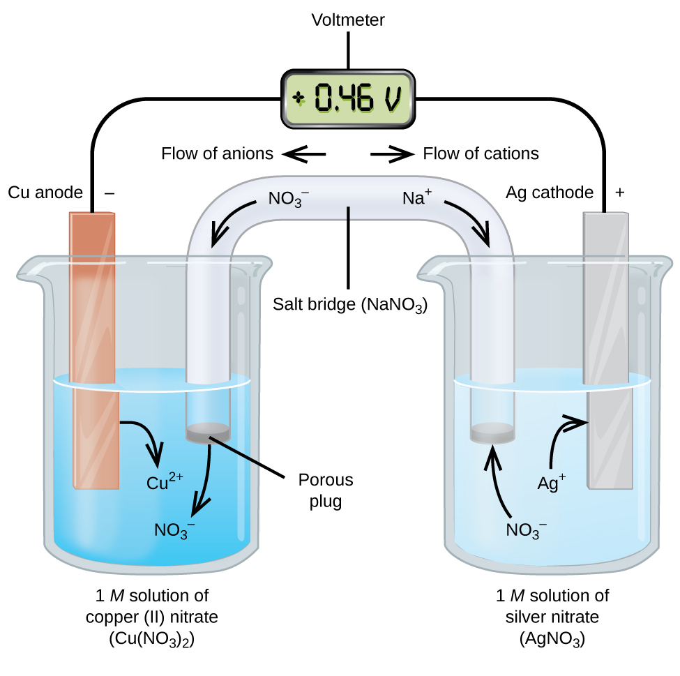
The beaker on the left side is called a half-cell, and contains a 1 M solution of copper(II) nitrate [Cu(NO3)2] with a piece of copper metal partially submerged in the solution. The copper metal is an electrode and is undergoing oxidation; therefore, the copper electrode is the anode. The anode is connected to a voltmeter with an electrically-conductive wire and the other terminal of the voltmeter is connected to a silver electrode. The silver is undergoing reduction; therefore, the silver electrode is the cathode. The half-cell on the right side consists of the silver electrode in a 1 M solution of silver nitrate (AgNO3).

At this point, no current flows—that is, no significant movement of electrons through the wire occurs because the circuit is open. The circuit is closed using a salt bridge, which allows for flow of ions. The salt bridge consists of a concentrated, nonreactive, electrolyte solution, such as the sodium nitrate (NaNO3) solution used in this example. As electrons flow from left to right through the electrode and wire, nitrate anions (NO3) pass through the porous plug on the left into the copper(II) nitrate solution. This keeps the beaker on the left electrically neutral by neutralizing the charge on the copper(II) ions that are produced in the solution as the copper metal is oxidized. At the same time, sodium cations (Na+) move to the right, through the porous plug, and into the silver nitrate solution. These added cations “replace” the silver ions that are removed from the solution as they are reduced to silver metal, keeping the beaker on the right electrically neutral. Without the salt bridge, the compartments cannot remain electrically neutral and no significant current would flow. However, if the two compartments are in direct contact, a salt bridge is not necessary.

The instant the circuit is completed with the addition of a salt bridge between the two half-cells, the voltmeter reads +0.46 V, this is called the cell potential. The cell potential is created when the two dissimilar metals are connected, and is a measure of the energy per unit charge available from the oxidation-reduction reaction. The volt is the derived SI unit for electrical potential:

[latex]\text{volt} = V = \frac{\text{J}}{\text{C}}[/latex]

In other words, volts must be multiplied by the charge in coulombs (C) to obtain the energy in joules (J).

When the electrochemical cell is constructed in this fashion, a positive cell potential indicates a spontaneous reaction and that the electrons are flowing from the anode to the cathode. There is a lot going on in Figure 4, so it is useful to summarize things for this system:

  • Electrons flow from the anode to the cathode: left to right in the standard galvanic cell in figure 4.
  • The electrode in the left half-cell is the anode because oxidation occurs here. (To help remember which is which: anions in the salt bridge flow toward it.)
  • The electrode in the right half-cell is the cathode because reduction occurs here. (To help remember which is which: cations in the salt bridge flow toward it.)
  • The cell potential, +0.46 V in this case, results from the inherent differences in the nature of the materials used to make the two half-cells.
  • The salt bridge must be present to close (complete) the circuit and both an oxidation and reduction must occur for current to flow.

There are many possible galvanic cells, so a shorthand notation is usually used to describe them. The cell notation (sometimes called a cell diagram) provides information about the various species involved in the reaction. A vertical line, |, denotes a phase boundary and a double line, ||, the salt bridge. Information about the anode is written to the left, followed by the anode solution, then the salt bridge (when present), then the cathode solution, and, finally, information about the cathode to the right. The cell notation for the galvanic cell in Figure 4 is then:

[latex]\text{Cu}(s){\mid}\text{Cu}^{2+}(aq\text{,}\;1\;M){\parallel}\text{Ag}^{+}(aq\text{,}\;1\;M){\mid}\text{Ag}(s)[/latex]

Note that spectator ions are not included and that the simplest form of each half-reaction is used. When known, the initial concentrations of the various ions are usually included.

One of the simplest cells is the Daniell cell. It is possible to construct this battery by placing a copper electrode at the bottom of a jar and covering the metal with a copper sulfate solution. A zinc sulfate solution is floated on top of the copper sulfate solution; then a zinc electrode is placed in the zinc sulfate solution. Connecting the copper electrode to the zinc electrode allows an electric current to flow. This is an example of a cell without a salt bridge, and ions may flow across the interface between the two solutions.

Some oxidation-reduction reactions involve species that are poor conductors of electricity, and so an electrode is used that does not participate in the reactions. Frequently, the electrode is platinum, gold, or graphite, all of which are inert to many chemical reactions. One such system is shown in Figure 5. Magnesium undergoes oxidation at the anode on the left and hydrogen ions undergo reduction at the cathode on the right. The reaction may be summarized as:

[latex]\begin{array}{lrcl} \text{oxidation:} & \text{Mg}(s) &\longrightarrow& \text{Mg}^{2+}(aq)\;+\;2\text{e}^{-} \\[0.5em] \text{reduction:} & 2\text{H}^{+}(aq)\;+\;2\text{e}^{-} &\longrightarrow& \text{H}_2(g) \\[0.5em] \hline \\[-0.25em] \text{overall:} & \text{Mg}(s)\;+\;2\text{H}^{+}(aq) &\longrightarrow& \text{Mg}^{2+}(aq)\;+\;\text{H}_2(g) \end{array}[/latex]

The cell used an inert platinum wire for the cathode, so the cell notation is:

[latex]\text{Mg}(s){\mid}\text{Mg}^{2+}(aq){\parallel}\text{H}^{+}(aq){\mid}\text{H}_2(g){\mid}\text{Pt}(s)[/latex]
This figure contains a diagram of an electrochemical cell. Two beakers are shown. Each is just over half full. The beaker on the left contains a colorless solution and is labeled “Solution of M g C l subscript 2.” The beaker on the right contains a colorless solution and is labeled “Solution of H C l.” A glass tube in the shape of an inverted U connects the two beakers at the center of the diagram. The tube contents are colorless. The ends of the tubes are beneath the surface of the solutions in the beakers and a small grey plug is present at each end of the tube. At the center of the diagram, the tube is labeled “Salt bridge. Each beaker shows a metal coils submerged in the liquid. The beaker on the left has a thin grey coiled strip that is labeled “M g coil.” The beaker on the right has a black wire that is oriented horizontally and coiled up in a spring-like appearance that is labeled “Non reactive platinum wire.” A wire extends across the top of the diagram that connects the ends of the M g strip and platinum wire just above the opening of each beaker. This wire is labeled “Conducting wire.” At the center of this wire above the two beakers near the center of the diagram is a right pointing arrow with the label “e superscript negative” at its base. Bubbles appear to be rising from the coiled platinum wire in the beaker. These bubbles are labeled “Bubbles of H subscript 2.” An arrow points down and to the right from a plus sign at the upper right region of the salt bride. An arrow points down and to the left from a negative sign at the upper left region of the salt bride. A curved arrow extends from the grey plug at the left end of the salt bridge into the surrounding solution in the left beaker. The label “Oxidation M g right pointing arrow M g superscript 2 plus plus 2 e superscript negative” appears beneath the left beaker. The label “Reduction 2 H superscript plus plus 2 e superscript negative right pointing arrow H subscript 2” appears beneath the right beaker.
Figure 5. The oxidation of magnesium to magnesium ion occurs in the beaker on the left side in this apparatus; the reduction of hydrogen ions to hydrogen occurs in the beaker on the right. A nonreactive, or inert, platinum wire allows electrons from the left beaker to move into the right beaker. The overall reaction is: Mg + 2H+ ⟶ Mg2+ + H2, which is represented in cell notation as: Mg(s) │ Mg2+(aq) ║ H+(aq) │ H2(g) │ Pt(s).

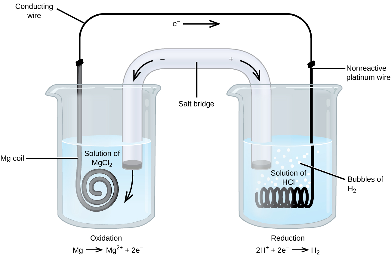
The magnesium electrode is an active electrode because it participates in the oxidation-reduction reaction. Inert electrodes, like the platinum electrode in Figure 5, do not participate in the oxidation-reduction reaction and are present so that current can flow through the cell. Platinum or gold generally make good inert electrodes because they are chemically unreactive.

Example 5

Using Cell Notation
Consider a galvanic cell consisted of

[latex]2\text{Cr}(s)\;+\;3\text{Cu}^{2+}(aq)\;{\longrightarrow}\;2\text{Cr}^{3+}(aq)\;+\;3\text{Cu}(s)[/latex]

Write the oxidation and reduction half-reactions and write the reaction using cell notation. Which reaction occurs at the anode? at the cathode?

Solution
By inspection, Cr is oxidized when three electrons are lost to form Cr3+, and Cu2+ is reduced as it gains two electrons to form Cu. Balancing the charge gives

[latex]\begin{array}{lrcl} \text{oxidation:} & 2\text{Cr}(s) &\longrightarrow& 2\text{Cr}^{3+}(aq)\;+\;6\text{e}^{-} \\[0.5em] \text{reduction:} & 3\text{Cu}^{2+}(aq)\;+\;6\text{e}^{-} &\longrightarrow& 3\text{Cu}(s) \\[0.5em] \hline \\[-0.25em] \text{overall:} & 2\text{Cr}(s)\;+\;3\text{Cu}^{2+}(aq) &\longrightarrow& 2\text{Cr}^{3+}(aq)\;+\;3\text{Cu}(s) \end{array}[/latex]

Cell notation uses the simplest form of each of the equations, and starts with the reaction at the anode. No concentrations were specified, so:

[latex]\text{Cr}(s){\mid}\text{Cr}^{3+}(aq){\parallel}\text{Cu}^{2+}(aq){\mid}\text{Cu}(s)[/latex]

Oxidation occurs at the anode and reduction at the cathode.

Using Cell Notation

Consider a galvanic cell consisted of

[latex]5\text{Fe}^{2+}(aq)\;+\;\text{MnO}_4^{\;\;-}(aq)\;+\;8\text{H}^{+}(aq)\;{\longrightarrow}\;5\text{Fe}^{3+}(aq)\;+\;\text{Mn}^{2+}(aq)\;+\;4\text{H}_2\text{O}(l)[/latex]

Write the oxidation and reduction half-reactions and write the reaction using cell notation. Which reaction occurs at the anode? at the cathode?

Solution
By inspection, Fe2+ undergoes oxidation when one electron is lost to form Fe3+, and MnO4 is reduced as it gains five electrons to form Mn2+. Balancing the charge gives

[latex]\begin{array}{lrcl} \text{oxidation:} & 5(\text{Fe}^{2+}(aq) &\longrightarrow& \text{Fe}^{3+}(aq)\;+\;\text{e}^{-}) \\[0.5em] \text{reduction:} & \text{MnO}_4^{\;\;-}(aq)\;+\;8\text{H}^{+}(aq)\;+\;5\text{e}^{-} &\longrightarrow& \text{Mn}^{2+}(aq)\;+\;4\text{H}_2\text{O}(l) \\[0.5em] \hline \\[-0.25em] \text{overall:} & 5\text{Fe}^{2+}(aq)\;+\;\text{MnO}_4^{\;\;-}(aq)\;+\;8\text{H}^{+}(aq) &\longrightarrow& 5\text{Fe}^{3+}(aq)\;+\;\text{Mn}^{2+}(aq)\;+\;4\text{H}_2\text{O}(l) \end{array}[/latex]

Cell notation uses the simplest form of each of the equations, and starts with the reaction at the anode. It is necessary to use an inert electrode, such as platinum, because there is no metal present to conduct the electrons from the anode to the cathode. No concentrations were specified so:

[latex]\text{Pt}(s){\mid}\text{Fe}^{2+}(aq)\text{,}\;\text{Fe}^{3+}(aq){\parallel}\text{MnO}_4^{\;\;-}(aq)\text{,}\;\text{H}^{+}(aq)\text{,}\;\text{Mn}^{2+}(aq){\mid}\text{Pt}(s)[/latex]

Oxidation occurs at the anode and reduction at the cathode.

Check Your Learning
Use cell notation to describe the galvanic cell where copper(II) ions are reduced to copper metal and zinc metal is oxidized to zinc ions.

Answer:

From the information given in the problem:

[latex]\begin{array}{lrcl} \text{anode (oxidation):} & \text{Zn}(s) &\longrightarrow& \text{Zn}^{2+}(aq)\;+\;2\text{e}^{-} \\[0.5em] \text{cathode (reduction):} & \text{Cu}^{2+}(aq)\;+\;2\text{e}^{-} &\longrightarrow& \text{Cu}(s) \\[0.5em] \hline \\[-0.25em] \text{overall:} & \text{Zn}(s)\;+\;\text{Cu}^{2+}(aq) &\longrightarrow& \text{Zn}^{2+}(aq)\;+\;\text{Cu}(s) \end{array}[/latex]

Using cell notation:
[latex]\text{Zn}(s){\mid}\text{Zn}^{2+}(aq){\parallel}\text{Cu}^{2+}(aq){\mid}\text{Cu}(s)[/latex].

Ch17.5 Standard Reduction Potential

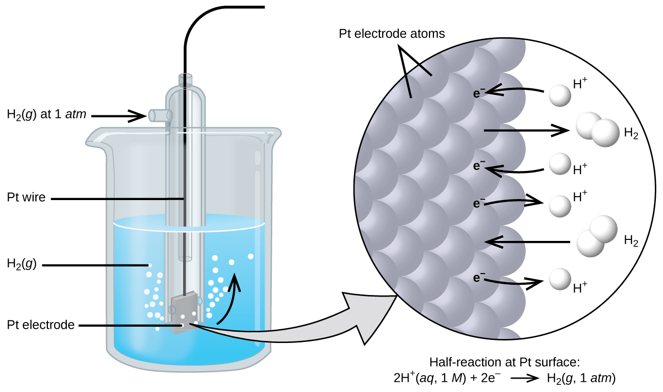
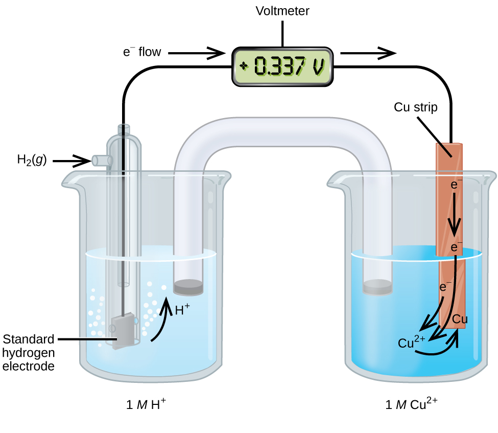
The cell potential in Figure 4 (+0.46 V) results from the difference in the electrical potentials for each electrode. While it is impossible to determine the electrical potential of a single electrode, we can assign an electrode the value of zero and then use it as a reference. The electrode chosen as the zero is shown in Figure 6 and is called the standard hydrogen electrode (SHE). The SHE consists of 1 atm of hydrogen gas bubbling through a 1 M HCl solution, usually at room temperature. Platinum, which is chemically inert, is used as the electrode. The reduction half-reaction chosen as the reference is:

[latex]2\text{H}^{+}(aq\text{,}\;1\;M)\;+\;2\text{e}^{-}\;{\rightleftharpoons}\;\text{H}_2(g\text{,}\;1\;\text{bar})\;\;\;\;\;\;E^{\circ} = 0\;\text{V}[/latex]

E° is the standard reduction potential. The superscript “°” denotes standard conditions (1 bar for gases, 1 M for solutes). Unless specified, the temperature is assumed to be 25 ºC.

The figure shows a beaker just over half full of a blue liquid. A glass tube is partially submerged in the liquid. Bubbles, which are labeled “H subscript 2 ( g )” are rising from the dark grey square, labeled “P t electrode” at the bottom of the tube. A curved arrow points up to the right, indicating the direction of the bubbles. A black wire which is labeled “P t wire” extends from the dark grey square up the interior of the tube through a small port at the top. A second small port extends out the top of the tube to the left. An arrow points to the port opening from the left. The base of this arrow is labeled “H subscript 2 ( g ) at 1 a t m.” A light grey arrow points to a diagram in a circle at the right that illustrates the surface of the P t electrode in a magnified view. P t atoms are illustrated as a uniform cluster of grey spheres which are labeled “P t electrode atoms.” On the grey atom surface, the label “e superscript negative” is shown 4 times in a nearly even vertical distribution to show electrons on the P t surface. A curved arrow extends from a white sphere labeled “H superscript plus” at the right of the P t atoms to the uppermost electron shown. Just below, a straight arrow extends from the P t surface to the right to a pair of linked white spheres which are labeled “H subscript 2.” A curved arrow extends from a second white sphere labeled “H superscript plus” at the right of the P t atoms to the second electron shown. A curved arrow extends from the third electron on the P t surface to the right to a white sphere labeled “H superscript plus.” Just below, an arrow points left from a pair of linked white spheres which are labeled “H subscript 2” to the P t surface. A curved arrow extends from the fourth electron on the P t surface to the right to a white sphere labeled “H superscript plus.” Beneath this atomic view is the label “Half-reaction at P t surface: 2 H superscript plus ( a q, 1 M ) plus 2 e superscript negative right pointing arrow H subscript 2 ( g, 1 a t m ).”
Figure 6. Hydrogen gas at 1 bar is bubbled through 1 M HCl solution. Platinum, which is inert to the action of the 1 M HCl, is used as the electrode. Electrons on the surface of the electrode combine with H+ in solution to produce hydrogen gas.

A galvanic cell consisting of a SHE and Cu2+/Cu half-cell can be used to determine the standard reduction potential for Cu2+ (Figure 7). In cell notation, the reaction is:

[latex]\text{Pt}(s){\mid}\text{H}_2(g\text{,\;}1\;\text{bar}){\mid}\text{H}^{+}(aq\text{,}\;1\;M){\parallel}\text{Cu}^{2+}(aq\text{,}\;1\;M){\mid}\text{Cu}(s)[/latex]

Electrons flow from the anode to the cathode. The reactions are:

[latex]\begin{array}{lrcl} \text{Anode (oxidation):} & \text{H}_2(g) &\longrightarrow& 2\text{H}^{+}(aq)\;+\;2\text{e}^{-} \\[0.5em] \text{Cathode (reduction):} & \text{Cu}^{2+}(aq)\;+\;2\text{e}^{-} &\longrightarrow& \text{Cu}(s) \\[0.5em] \hline \\[-0.25em] \text{Overall:} & \text{Cu}^{2+}(aq)\;+\;\text{H}_2(g) &\longrightarrow& 2\text{H}^{+}(aq)\;+\;\text{Cu}(s) \end{array}[/latex]

The standard reduction potential of the galvanic cell can be determined by subtracting the standard reduction potential for the reaction occurring at the anode from the standard reduction potential for the reaction occurring at the cathode. The minus sign is necessary because oxidation is the reverse of reduction.

[latex]E_{\text{cell}}^{\circ} = E_{\text{cathode}}^{\circ}\;-\;E_{\text{anode}}^{\circ}[/latex]
[latex]+0.34\;\text{V} = E_{\text{Cu}^{2+}/\text{Cu}}^{\circ}\;-\;E_{\text{H}^{+}/\text{H}_2}^{\circ} = E_{\text{Cu}^{2+}/\text{Cu}}^{\circ}\;-\;0 = E_{\text{Cu}^{2+}/\text{Cu}}^{\circ}[/latex]
This figure contains a diagram of an electrochemical cell. Two beakers are shown. Each is just over half full. The beaker on the left contains a clear, colorless solution and is labeled below as “1 M H superscript plus.” The beaker on the right contains a blue solution and is labeled below as “1 M C u superscript 2 plus.” A glass tube in the shape of an inverted U connects the two beakers at the center of the diagram. The tube contents are colorless. The ends of the tubes are beneath the surface of the solutions in the beakers and a small grey plug is present at each end of the tube. The beaker on the left has a glass tube partially submersed in the liquid. Bubbles are rising from the grey square, labeled “Standard hydrogen electrode” at the bottom of the tube. A curved arrow points up to the right, indicating the direction of the bubbles. A black wire extends from the grey square up the interior of the tube through a small port at the top to a rectangle with a digital readout of “positive 0.337 V” which is labeled “Voltmeter.” A second small port extends out the top of the tube to the left. An arrow points to the port opening from the left. The base of this arrow is labeled “H subscript 2 ( g ).” The beaker on the right has an orange-brown strip that is labeled “C u strip” at the top. A wire extends from the top of this strip to the voltmeter. An arrow points toward the voltmeter from the left which is labeled “e superscript negative flow.” Similarly, an arrow points away from the voltmeter to the right. A curved arrow extends from the standard hydrogen electrode in the beaker on the left into the surrounding solution. The tip of this arrow is labeled “H plus.” An arrow points downward from the label “e superscript negative” on the C u strip in the beaker on the right. A second curved arrow extends from another “e superscript negative” label into the solution below toward the label “C u superscript 2 plus” in the solution. A third “e superscript negative” label positioned at the lower left edge of the C u strip has a curved arrow extending from it to the “C u superscript 2 plus” label in the solution. A curved arrow extends from this “C u superscript 2 plus” label to a “C u” label at the lower edge of the C u strip.
Figure 7. A galvanic cell can be used to determine the standard reduction potential of Cu2+.

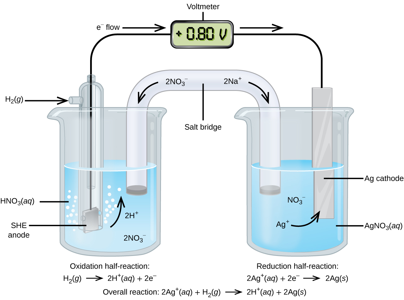
Using the SHE as a reference, other standard reduction potentials can be determined. Consider the cell shown in Figure 8, where:

[latex]\text{Pt}(s){\mid}\text{H}_2(g\text{,\;}1\;\text{bar}){\mid}\text{H}^{+}(aq\text{,\;}1\;M){\parallel}\text{Ag}^{+}(aq\text{,\;}1\;M){\mid}\text{Ag}(s)[/latex]

Electrons flow from left to right, and the reactions are:

[latex]\begin{array}{lrcl} \text{anode (oxidation):} & \text{H}_2(g) &\longrightarrow& 2\text{H}^{+}(aq)\;+\;2\text{e}^{-} \\[0.5em] \text{cathode (reduction):} & 2\text{Ag}^{+}(aq)\;+\;2\text{e}^{-} &\longrightarrow& 2\text{Ag}(s) \\[0.5em] \hline \\[-0.25em] \text{overall:} & 2\text{Ag}^{+}(aq)\;+\;\text{H}_2(g) &\longrightarrow& 2\text{H}^{+}(aq)\;+\;2\text{Ag}(s) \end{array}[/latex]

[latex]E_{\text{cell}}^{\circ}[/latex] can be determined by subtracting the standard reduction potential for the reaction occurring at the anode from the standard reduction potential for the reaction occurring at the cathode. The minus sign is needed because oxidation is the reverse of reduction.

[latex]E_{\text{cell}}^{\circ} = E_{\text{cathode}}^{\circ}\;-\;E_{\text{anode}}^{\circ}[/latex]
[latex]+0.80\;\text{V} = E_{\text{Ag}^{+}/\text{Ag}}^{\circ}\;-\;E_{\text{H}^{+}/\text{H}_2}^{\circ} = E_{\text{Ag}^{+}/\text{Ag}}^{\circ}\;-\;0 = E_{\text{Ag}^{+}/\text{Ag}}^{\circ}[/latex]

It is important to note that the potential is not doubled for the cathode reaction.

This figure contains a diagram of an electrochemical cell. Two beakers are shown. Each is just over half full. The beaker on the left contains a clear, colorless solution which is labeled “H N O subscript 3 ( a q ).” The beaker on the right contains a clear, colorless solution which is labeled “A g N O subscript 3 ( a q ).” A glass tube in the shape of an inverted U connects the two beakers at the center of the diagram and is labeled “Salt bridge.” The tube contents are colorless. The ends of the tubes are beneath the surface of the solutions in the beakers and a small grey plug is present at each end of the tube. The label “2 N a superscript plus” appears on the upper right portion of the tube. A curved arrow extends from this label down and to the right. The label “2 N O subscript 3 superscript negative” appears on the upper left portion of the tube. A curved arrow extends from this label down and to the left. The beaker on the left has a glass tube partially submerged in the liquid. Bubbles are rising from the grey square, labeled “SHE anode” at the bottom of the tube. A curved arrow points up to the right. The labels “2 H superscript plus” and “2 N O subscript 3 superscript negative” appear on the liquid in the beaker. A black wire extends from the grey square up the interior of the tube through a small port at the top to a rectangle with a digital readout of “positive 0.80 V” which is labeled “Voltmeter.” A second small port extends out the top of the tube to the left. An arrow points to the port opening from the left. The base of this arrow is labeled “H subscript 2 ( g ).” The beaker on the right has a silver strip that is labeled “A g cathode.” A wire extends from the top of this strip to the voltmeter. An arrow points toward the voltmeter from the left which is labeled “e superscript negative flow.” Similarly, an arrow points away from the voltmeter to the right. The solution in the beaker on the right has the labels “N O subscript 3 superscript negative” and “A g superscript plus” on the solution. A curved arrow extends from the A g superscript plus label to the A g cathode. Below the left beaker at the bottom of the diagram is the label “Oxidation half-reaction: H subscript 2 ( g ) right pointing arrow 2 H superscript plus ( a q ) plus 2 e superscript negative.” Below the right beaker at the bottom of the diagram is the label “Reduction half-reaction: 2 A g superscript plus ( a q ) right pointing arrow 2 A g ( s ).”
Figure 8. A galvanic cell can be used to determine the standard reduction potential of Ag+. The SHE on the left is the anode and assigned a standard reduction potential of zero.

The SHE is rather dangerous and rarely used in the laboratory. Its main significance is that it establishes the zero for standard reduction potentials. Once determined, standard reduction potentials can be used to determine the standard cell potential, [latex]E_{\text{cell}}^{\circ}[/latex], for any cell. For example, for the cell shown in Figure 4:

[latex]\text{Cu}(s){\mid}\text{Cu}^{2+}(aq\text{,\;}1\;M){\parallel}\text{Ag}^{+}(aq\text{,\;}1\;M){\mid}\text{Ag}(s)[/latex]
[latex]\begin{array}{lrcl} \text{anode (oxidation):} & \text{Cu}(s) &\longrightarrow& \text{Cu}^{2+}(aq)\;+\;2\text{e}^{-} \\[0.5em] \text{cathode (reduction):} & 2\text{Ag}^{+}(aq)\;+\;2\text{e}^{-} &\longrightarrow& 2\text{Ag}(s) \\[0.5em] \hline \\[-0.25em] \text{overall:} & \text{Cu}(s)\;+\;2\text{Ag}^{+}(aq) &\longrightarrow& \text{Cu}^{2+}(aq)\;+\;2\text{Ag}(s) \end{array}[/latex]
[latex]E_{\text{cell}}^{\circ} = E_{\text{cathode}}^{\circ}\;-\;E_{\text{anode}}^{\circ} = E_{\text{Ag}^{+}/\text{Ag}}^{\circ}\;-\;E_{\text{Cu}^{2+}/\text{Cu}}^{\circ} = 0.80\;\text{V}\;-\;0.34\;\text{V} = 0.46\;\text{V}[/latex]

Again, note that when calculating [latex]E_{\text{cell}}^{\circ}[/latex], standard reduction potentials always remain the same even when a half-reaction is multiplied by a factor. Standard reduction potentials for selected reduction reactions are shown in appendix.

Tables like this make it possible to determine the standard cell potential for many oxidation-reduction reactions.

Example 6

Cell Potentials from Standard Reduction Potentials
What is the standard cell potential for a galvanic cell that consists of Au3+/Au and Ni2+/Ni half-cells? Identify the oxidizing and reducing agents.

Solution
Using appendix, the reactions involved in the galvanic cell, both written as reductions, are:

[latex]\text{Au}^{3+}(aq)\;+\;3\text{e}^{-}\;{\longrightarrow}\;\text{Au}(s)\;\;\;\;\;\;\;E_{\text{Au}^{3+}/\text{Au}}^{\circ} = +1.52\;\text{V}[/latex]
[latex]\text{Ni}^{2+}(aq)\;+\;2\text{e}^{-}\;{\longrightarrow}\;\text{Ni}(s)\;\;\;\;\;\;\;E_{\text{Ni}^{2+}/\text{Ni}}^{\circ} = -0.25\;\text{V}[/latex]

The reduction reactions are reversible. Since galvanic cells have positive cell potentials, the reaction at the anode will be the half-reaction with the smaller or more negative standard reduction potential. Reversing the reaction at the anode (to show the oxidation) but not its standard reduction potential gives:

[latex]\begin{array}{lrcll} \text{Anode (oxidation):} & \text{Ni}(s) &\longrightarrow& \text{Ni}^{2+}(aq)\;+\;2\text{e}^{-} & E_{\text{anode}}^{\circ} = E_{\text{Ni}^{2+}/\text{Ni}}^{\circ} = -0.25\;\text{V} \\[0.5em] \text{Cathode (reduction):} & \text{Au}^{3+}(aq)\;+\;3\text{e}^{-} &\longrightarrow& \text{Au}(s) & E_{\text{cathode}}^{\circ} = E_{\text{Au}^{3+}/\text{Au}}^{\circ} = +1.52\;\text{V} \end{array}[/latex]

The least common factor is six, so the overall reaction is

[latex]3\text{Ni}(s)\;+\;2\text{Au}^{3+}(aq)\;{\longrightarrow}\;3\text{Ni}^{2+}(aq)\;+\;2\text{Au}(s)[/latex]

The reduction potentials are not scaled by the stoichiometric coefficients when calculating the cell potential, and the unmodified standard reduction potentials must be used.

[latex]E_{\text{cell}}^{\circ} = E_{\text{cathode}}^{\circ}\;-\;E_{\text{anode}}^{\circ} = 1.52\;\text{V}\;-\;(-0.25\;\text{V}) = 1.77\;\text{V}[/latex]

From the half-reactions, Ni is oxidized, so it is the reducing agent, and Au3+ is reduced, so it is the oxidizing agent.

Check Your Learning
A galvanic cell consists of a Mg electrode in 1 M Mg(NO3)2 solution and a Ag electrode in 1 M AgNO3 solution. Calculate the standard cell potential at 25 °C.

Answer:

[latex]\text{Mg}(s)\;+\;2\text{Ag}^{+}(aq)\;{\longrightarrow}\;\text{Mg}^{2+}(aq)\;+\;2\text{Ag}(s)\;\;\;\;\;\;\;E_{\text{cell}}^{\circ} = 0.7991\;\text{V}\;-\;(-2.356\;\text{V}) = 3.155\;\text{V}[/latex]

Ch17.6 ΔG°, K°, and E°cell

Similar to the reactions we’ve studied before, redox reactions have thermodynamical characteristics that can be described by ΔG° (Gibbs free energy) and (the equilibrium constant), which can be related to [latex]E_{\text{cell}}^{\circ}[/latex], as they all can tell us whether the redox reaction is reactant-favored or product-favored.

In galvanic cells, chemical energy is converted into electrical energy, which can do work. The electrical work is the product of the charge transferred multiplied by the potential difference (voltage):

[latex]\text{electrical work (J)} = \text{volts}\;\times\;(\text{charge in coulombs})[/latex]

The charge on 1 mole of electrons is known as the Faraday’s constant (F):

[latex]F = \frac{6.0221\;\times\;10^{23}\text{e}^{-}}{mol}\;\times\;\frac{1.6022\;\times\;10^{-19}\;\text{C}}{\text{e}^{-}} = 96485\;\frac{\text{C}}{\text{mol}} = 96485\frac{\text{J}}{\text{V}{\cdot}\text{mol}}[/latex]

Hence, the total quantity of charge transferred is:

[latex]\text{total charge} = (\text{number of moles of e}^{-})\;\times\;F = nF[/latex]

where n is the number of moles of electrons for the balanced oxidation-reduction reaction.

The measured cell potential is the maximum potential the cell can produce and is related to the electrical work (wele) by

[latex]E_\text{cell} = \frac{-w_{\text{ele}}}{nF}\;\;\;\;\;\;\;\text{or}\;\;\;\;\;\;\;w_{\text{ele}} = -nFE_{\text{cell}}[/latex]

The negative sign for the work indicates that the electrical work is done by the system (the galvanic cell) on the surroundings. As we’ve learned earlier, the free energy is defined as the energy that is available to do work. In particular, the change in free energy is defined in terms of the maximum work (wmax), which, for electrochemical systems, is wele.

[latex]{\Delta}G = w_{\text{max}} = w_{\text{ele}} = -nFE_{\text{cell}}[/latex]

We know that the signs are correct when we consider that n and F are positive constants and galvanic cells, which have positive cell potentials, involve spontaneous reactions. Thus, spontaneous reactions, which have ΔG < 0, must have Ecell > 0. If all the reactants and products are in their standard states, this becomes

[latex]{\Delta}G^{\circ} = -nFE_{\text{cell}}^{\circ}[/latex]

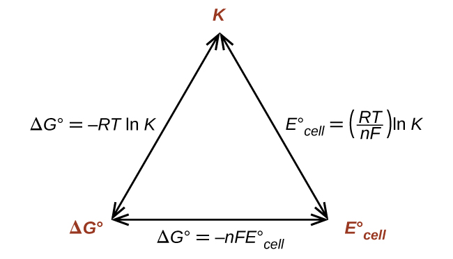
This also provides a way to relate standard cell potentials to equilibrium constants, since:

[latex]{\Delta}G^{\circ} = -RT\;\text{ln}\;K^{\circ}[/latex]
[latex]-nFE_{\text{cell}}^{\circ} = -RT\;\text{ln}\;K^{\circ}\;\;\;\;\;\;\;\text{or}\;\;\;\;\;\;\;E_{\text{cell}}^{\circ} = \frac{RT}{nF}\;\text{ln}\;K^{\circ}[/latex]

Thus, if ΔG°, , or [latex]E_{\text{cell}}^{\circ}[/latex] is known or can be calculated, the other two quantities can be readily determined. The relationships are shown graphically in Figure 9.

A diagram is shown that involves three double headed arrows positioned in the shape of an equilateral triangle. The vertices are labeled in red. The top vertex is labeled “K.“ The vertex at the lower left is labeled “delta G superscript degree symbol.” The vertex at the lower right is labeled “E superscript degree symbol subscript cell.” The right side of the triangle is labeled “E superscript degree symbol subscript cell equals ( R T divided by n F ) l n K.” The lower side of the triangle is labeled “delta G superscript degree symbol equals negative n F E superscript degree symbol subscript cell.” The left side of the triangle is labeled “delta G superscript degree symbol equals negative R T l n K.”
Figure 9. The relationships between ΔG°, K°, and E°cell. Given any one of the three quantities, the other two can be calculated, and any of the quantities can be used to determine whether a process is spontaneous.

Example 7

Equilibrium Constants, Standard Cell Potentials, and Standard Free Energy Changes
What is the standard free energy change and equilibrium constant for the following reaction at 25 °C?

[latex]2\text{Ag}^{+}(aq)\;+\;\text{Fe}(s)\;{\leftrightharpoons}\;2\text{Ag}(s)\;+\;\text{Fe}^{2+}(aq)[/latex]

Solution
The reaction involves an oxidation-reduction reaction, so the standard cell potential can be calculated using the data [latex]E_{\text{Fe}^{2+}/\text{Fe}}^{\circ} = -0.44\;\text{V}[/latex] and [latex]E_{\text{Ag}^{+}/\text{Ag}}^{\circ} = 0.7991;\text{V}[/latex] for the half reactions:

[latex]\begin{array}{lrcll} \text{anode (oxidation):} & \text{Fe}(s) &\longrightarrow& \text{Fe}^{2+}(aq)\;+\;2\text{e}^{-} \\[0.5em] \text{cathode (reduction):} & 2\;\times\;(\text{Ag}^{+}(aq)\;+\;\text{e}^{-} &\longrightarrow& \text{Ag}(s)) \end{array}[/latex]
[latex]E_{\text{cell}}^{\circ} = E_{\text{cathode}}^{\circ}\;-\;E_{\text{anode}}^{\circ} = E_{\text{Ag}^{+}/\text{Ag}}^{\circ}\;-\;E_{\text{Fe}^{2+}/\text{Fe}}^{\circ} = +1.24\;\text{V}[/latex]

Remember that the cell potential for the cathode is not doubled here when determining the standard cell potential.

With n = 2, the equilibrium constant is:

[latex]E_{\text{cell}}^{\circ} = \frac{RT}{nF}\;\text{ln}\;K^{\circ}\;\;\;\;\;\text{or}\;\;\;\;\;\text{ln}\;K^{\circ} = \frac{nFE_{\text{cell}}^{\circ}}{RT}[/latex]
[latex]\begin{array}{r @{{}={}} l}\text{ln}\;K^{\circ} & \frac{(2)(96485\;\text{J}/\text{V}{\cdot}\text{mol})(1.24\;\text{V})}{(8.314\;\text{J}/\text{K}{\cdot}\text{mol})(298\;\text{K})} \\[0.5em] \text{ln}\;K^{\circ} & 96.6 \\[0.5em] K^{\circ} & e^{96.6} = 9\;\times\;10^{41} \end{array}[/latex]

The standard free energy is:

[latex]{\Delta}G^{\circ} = -nFE_{\text{cell}}^{\circ}[/latex]
[latex]{\Delta}G^{\circ} = -2\;\times\;96485\;\frac{\text{J}}{\text{V}{\cdot}\text{mol}}\;\times\;1.24\;\text{V} = -239\;\frac{\text{kJ}}{\text{mol}}[/latex]

Check your answer: A positive standard cell potential means a spontaneous reaction, so the standard free energy change should be negative, and an equilibrium constant should be >1.

Check Your Learning
What is the standard free energy change and the equilibrium constant for the following reaction at room temperature? Is the reaction spontaneous?

[latex]\text{Sn}(s)\;+\;2\text{Cu}^{2+}(aq)\;{\leftrightharpoons}\;\text{Sn}^{2+}(aq)\;+\;2\text{Cu}^{+}(aq)[/latex]

Answer:

n = 2; [latex]E_{\text{cell}}^{\circ} = +0.297\;\text{V;}\;{\Delta}G^{\circ} = -57.3\;\frac{\text{kJ}}{\text{mol}}[/latex]; K = 1 × 10¹⁰.

The reaction is spontaneous.

Ch17.7 Nernst Equation

Now that the connection has been made between the free energy and cell potentials, nonstandard concentrations follow. Recall that

[latex]{\Delta}G = {\Delta}G^{\circ}\;+\;RT\;\text{ln}\;Q[/latex]

where Q is the reaction quotient. Converting to cell potentials:

[latex]-nFE_{\text{cell}} = -nFE_{\text{cell}}^{\circ}\;+\;RT\;\text{ln}\;Q\;\;\;\;\;\;\;\text{or}\;\;\;\;\;\;\;E_{\text{cell}} = E_{\text{cell}}^{\circ}\;-\;\frac{RT}{nF}\;\text{ln}\;Q[/latex]

This is the Nernst equation. With this equation, it is possible to calculate the cell potential at nonstandard conditions. This adjustment is necessary because potentials determined under different conditions will have different values.

Example 8

Cell Potentials at Nonstandard Conditions
Consider the following reaction at room temperature:

[latex]\text{Co}(s)\;+\;\text{Fe}^{2+}(aq\text{, }1.94\;M)\;{\longrightarrow}\;\text{Co}^{2+}(aq\text{, }0.15\;M)\;+\;\text{Fe}(s)[/latex]

Is the process spontaneous?

Solution
There are two ways to solve the problem: (1) If thermodynamic information are available, you can calculate the free energy change. If the free energy change is negative, the process is spontaneous. (2) If standard half-cell potential information are available, you can calculate the cell potential. If the cell potential is positive, the process is spontaneous.

We will use approach (2) here. The half reactions involved in the given reaction are listed below, with standared half-cell potentials of [latex]E_{\text{Co}^{2+}/\text{Co}}^{\circ} = -0.277\;\text{V}[/latex] and [latex]E_{\text{Fe}^{2+}/\text{Fe}}^{\circ} = -0.44\;\text{V}[/latex]:

[latex]\begin{array}{lrcll} \text{Anode (oxidation):} & \text{Co}(s) &\longrightarrow& \text{Co}^{2+}(aq)\;+\;2\text{e}^{-} \\[0.5em] \text{Cathode (reduction):} & \text{Fe}^{2+}(aq)\;+\;2\text{e}^{-} &\longrightarrow& \text{Fe}(s) \end{array}[/latex]
[latex]E_{\text{cell}}^{\circ} = E_{\text{cathode}}^{\circ}\;-\;E_{\text{anode}}^{\circ} = -0.44\;\text{V}\;-\;(-0.277\;\text{V}) = -0.16\;\text{V}[/latex]

The process is not spontaneous under standard conditions.

Using the Nernst equation, given the concentrations stated in the problem and n = 2:

[latex]Q = \frac{[\text{Co}^{2+}]}{[\text{Fe}^{2+}]} = \frac{0.15\;M}{1.94\;M} = 0.077[/latex]
[latex]\begin{array}{rcl} E_{\text{cell}} &=& E_{\text{cell}}^{\circ}\;-\;\frac{RT}{nF}\;\text{ln}\;Q \\[0.5em] &=& -0.16\;\text{V}\;\frac{(8.314\;\text{J}/\text{K}{\cdot}\text{mol})(298\;\text{K})}{(2)(96485\;\text{J}/\text{V}{\cdot}\text{mol})}\;\text{ln}(0.077) \\[0.5em] &=& -0.16\;\text{V}\;+\;0.033\;\text{V} = -0.013\;\text{V}\end{array}[/latex]

The process is nonspontaneous under the given conditions.

Check Your Learning
What is the cell potential for the following reaction at room temperature?

[latex]\text{Al}(s){\mid}\text{Al}^{3+}(aq\text{,\;}0.15\;M){\parallel}\text{Cu}^{2+}(aq\text{,\;}0.025\;M){\mid}\text{Cu}(s)[/latex]

What are the values of n and Q for the overall reaction? Is the reaction spontaneous under these conditions?

Answer:

n = 6; Q = 1440; Ecell = +1.98 V, spontaneous.

Ch17.8 Concentration Cells

A concentration cell is a special type of cell where the electrodes are the same material and the half-cells differ only in concentration. Since one or both compartments is not standard, the cell potentials will be unequal; therefore, there will be a potential difference, which can be determined with the aid of the Nernst equation.

Example 9

Concentration Cells
What is the cell potential of the concentration cell described by

[latex]\text{Zn}(s){\mid}\text{Zn}^{2+}(aq\text{,\;}0.10\;M){\parallel}\text{Zn}^{2+}(aq\text{,\;}0.50\;M){\mid}\text{Zn}(s)[/latex]

Solution
From the information given:

[latex]\begin{array}{lrcll} \text{Anode:} & \text{Zn}(s) &\longrightarrow& \text{Zn}^{2+}(aq\text{, }0.10\;M)\;+\;2\text{e}^{-} & E_{\text{anode}}^{\circ} = -0.763\;\text{V} \\[0.5em] \text{Cathode:} & \text{Zn}^{2+}(aq\text{, }0.50\;M)\;+\;2\text{e}^{-} &\longrightarrow& \text{Zn}(s) & E_{\text{cathode}}^{\circ} = -0.763\;\text{V} \\[0.5em] \hline \\[-0.25em] \text{Overall:} & \text{Zn}^{2+}(aq\text{, }0.50\;M) &\longrightarrow& \text{Zn}^{2+}(aq\text{, }0.10\;M) & E_{\text{cell}}^{\circ} = 0.000\;\text{V} \end{array}[/latex]

The standard cell potential is zero because the anode and cathode involve the same reaction; only the concentration of Zn2+ changes. Substituting into the Nernst equation,

[latex]E_{\text{cell}} = 0.000\;\text{V}\;-\;\frac{(8.314\;\text{J}/\text{K}{\cdot}\text{mol})(298\;\text{K})}{(2)(96485\;\text{J}/\text{V}{\cdot}\text{mol})}\;\text{ln}(\frac{0.10\;\text{M}}{0.50\;\text{M}}) = +0.021\;\text{V}[/latex]

The process is spontaneous at these conditions.

Check your answer: In a concentration cell, the standard cell potential will always be zero. To get a positive cell potential (spontaneous process) the reaction quotient Q must be <1.

Check Your Learning
What value of Q for the previous concentration cell would result in a voltage of 0.10 V? If the concentration of zinc ion at the cathode was 0.50 M, what was the concentration at the anode?

Answer:

Q = 0.00042; [Zn2+]cat = 2.1 × 10⁻⁴M.

Ch17.9 Batteries

A battery is an electrochemical cell or series of cells that produces an electric current. In principle, any galvanic cell can be used as a battery. An ideal battery would never run down, produce an unchanging voltage, and be capable of withstanding environmental extremes of heat and humidity. Real batteries strike a balance between ideal characteristics and practical limitations. For example, the mass of a car battery is about 18 kg or about 1% of the mass of an average car or light-duty truck. This type of battery would supply nearly unlimited energy if used in a smartphone, but would be rejected for this application because of its mass. Thus, no single battery is “best” and batteries are selected for a particular application, keeping things like the mass of the battery, its cost, reliability, and current capacity in mind. There are two basic types of batteries: primary and secondary. A few batteries of each type are described next.

Ch17.10 Primary Batteries

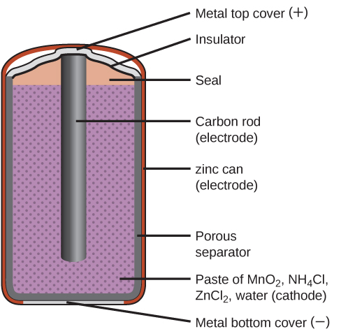
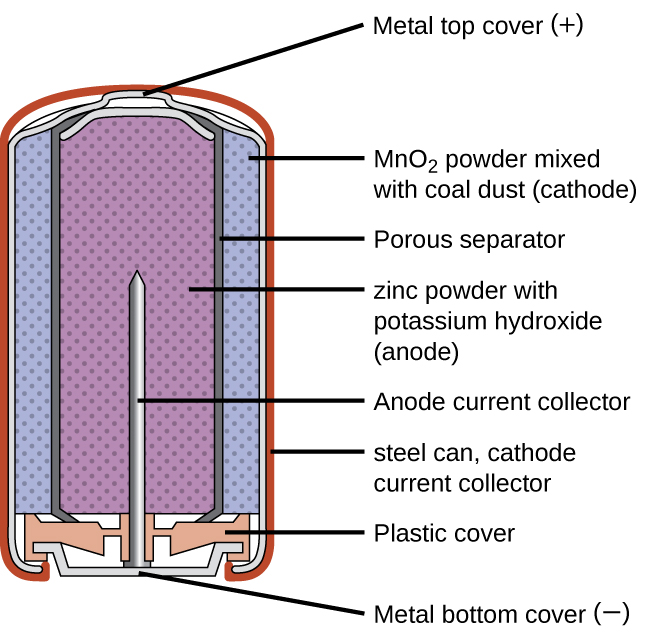
Primary batteries are single-use batteries because they cannot be recharged. A common primary battery is the dry cell (Figure 10), which is a zinc-carbon battery. The zinc serves as both a container and the negative electrode. The positive electrode is a rod made of carbon that is surrounded by a paste of manganese(IV) oxide, zinc chloride, ammonium chloride, carbon powder, and a small amount of water. The reaction at the anode can be represented as the ordinary oxidation of zinc:

[latex]\text{Zn}(s)\;{\longrightarrow}\;\text{Zn}^{2+}(aq)\;+\;2\text{e}^{-}\;\;\;\;\;\;\;E_{\text{Zn}^{2+}/\text{Zn}}^{\circ} = -0.7618\;\text{V}[/latex]

The reaction at the cathode is more complicated, in part because more than one reaction occurs. The series of reactions that occurs at the cathode is approximately:

[latex]2\text{MnO}_2(s)\;+\;2\text{NH}_4\text{Cl}(aq)\;+\;2\text{e}^{-}\;{\longrightarrow}\;\text{Mn}_2\text{O}_3(s)\;+\;2\text{NH}_3(aq)\;+\;\text{H}_2\text{O}(l)\;+\;2\text{Cl}^{-}[/latex]

The overall reaction for the zinc–carbon battery can be represented as:

[latex]2\text{MnO}_2(s)\;+\;2\text{NH}_4\text{Cl}(aq)\;+\;\text{Zn}(s)\;{\longrightarrow}\;\text{Zn}^{2+}(aq)\;+\;\text{Mn}_2\text{O}_3(s)\;+\;2\text{NH}_3(aq)\;+\;\text{H}_2\text{O}(l)\;+\;2\text{Cl}^{-}[/latex]

with an overall cell potential of about 1.5 V initially, and decreases as the battery is used. It is important to remember that the voltage delivered by a battery is the same regardless of the size of a battery. For this reason, D, C, A, AA, and AAA batteries all have the same voltage rating. However, larger batteries can deliver more moles of electrons. As the zinc container oxidizes, its contents eventually leak out, so this type of battery should not be left in any electrical device for extended periods.

A diagram of a cross section of a dry cell battery is shown. The overall shape of the cell is cylindrical. The lateral surface of the cylinder, indicated as a thin red line, is labeled “zinc can (electrode).” Just beneath this is a slightly thicker dark grey surface that covers the lateral surface, top, and bottom of the battery, which is labeled “Porous separator.” Inside is a purple region with many evenly spaced small darker purple dots, labeled “Paste of M n O subscript 2, N H subscript 4 C l, Z n C l subscript 2, water (cathode).” A dark grey rod, labeled “Carbon rod (electrode),” extends from the top of the battery, leaving a gap of less than one-fifth the height of the battery below the rod to the bottom of the cylinder. A thin grey line segment at the very bottom of the cylinder is labeled “Metal bottom cover (negative).” The very top of the cylinder has a thin grey surface that curves upward at the center over the top of the carbon electrode at the center of the cylinder. This upper surface is labeled “Metal top cover (positive).” A thin dark grey line just below this surface is labeled “Insulator.” Below this, above the purple region, and outside of the carbon electrode at the center is an orange region that is labeled “Seal.”
Figure 10. The diagram shows a cross section of a flashlight battery, a zinc-carbon dry cell.

Alkaline batteries (Figure 11) were developed in the 1950s partly to address some of the performance issues with zinc–carbon dry cells. They are manufactured to be exact replacements for zinc-carbon dry cells. As their name suggests, these types of batteries use alkaline electrolytes, often potassium hydroxide. The reactions are:

[latex]\begin{array}{lrcll} \text{anode:} & \text{Zn}(s)\;+\;2\text{OH}^{-}(aq) &\longrightarrow& \text{ZnO}(s)\;+\;\text{H}_2\text{O}(l)\;+\;2\text{e}^{-} & E_{\text{anode}}^{\circ} = -1.28\;\text{V} \\[0.5em] \text{cathode:} & 2\text{MnO}_2(s)\;+\;\text{H}_2\text{O}(l)\;+\;2\text{e}^{-} &\longrightarrow& \text{Mn}_2\text{O}_3(s)\;+\;2\text{OH}^{-}(aq) & E_{\text{cathode}}^{\circ} = +0.15\;\text{V} \\[0.5em] \hline \\[-0.25em] \text{overall:} & \text{Zn}(s)\;+\;2\text{MnO}_2(s) &\longrightarrow& \text{ZnO}(s)\;+\;\text{Mn}_2\text{O}_3(s) & E_{\text{cell}}^{\circ} = +1.43\;\text{V} \end{array}[/latex]

An alkaline battery can deliver about three to five times the energy of a zinc-carbon dry cell of similar size. Alkaline batteries are prone to leaking potassium hydroxide, so these should also be removed from devices for long-term storage. While some alkaline batteries are rechargeable, most are not. Attempts to recharge an alkaline battery that is not rechargeable often leads to rupture of the battery and leakage of the potassium hydroxide electrolyte.

A diagram of a cross section of an alkaline battery is shown. The overall shape of the cell is cylindrical. The lateral surface of the cylinder, indicated as a thin red line, is labeled “Outer casing.” Just beneath this is a thin, light grey surface that covers the lateral surface and top of the battery. Inside is a blue region with many evenly spaced small darker dots, labeled “M n O subscript 2 (cathode).” A thin dark grey layer is just inside, which is labeled “Ion conducting separator.” A purple region with many evenly spaced small darker dots fills the center of the battery and is labeled “ zinc (anode).” The very top of the battery has a thin grey curved surface over the central purple region. The curved surface above is labeled “Positive connection (plus).” At the base of the battery, an orange structure, labeled “Protective cap,” is located beneath the purple and blue central regions. This structure holds a grey structure that looks like a nail with its head at the bottom and pointed end extending upward into the center of the battery. This nail-like structure is labeled “Current pick up.” At the very bottom of the battery is a thin grey surface that is held by the protective cap. This surface is labeled “Negative terminal (negative).”
Figure 11. Alkaline batteries were designed as direct replacements for zinc-carbon (dry cell) batteries.

Ch17.11 Secondary Batteries

Secondary batteries are rechargeable. These are the types of batteries found in devices such as smartphones, electronic tablets, and automobiles.

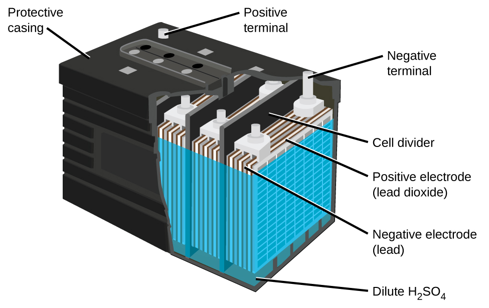
The lead acid battery (Figure 12) is the type of secondary battery used in your automobile. It is inexpensive and capable of producing the high current required by automobile starter motors. The reactions for a lead acid battery are:

[latex]\begin{array}{lrcl} \text{anode:} & \text{Pb}(s)\;+\;\text{HSO}_4^{\;\;-}(aq) &\longrightarrow& \text{PbSO}_4(s)\;+\;\text{H}^{+}(aq)\;+\;2\text{e}^{-} \\[0.5em] \text{cathode:} & \text{PbO}_2(s)\;+\;\text{HSO}_4^{\;\;-}(aq)\;+\;3\text{H}^{+}(aq)\;+\;2\text{e}^{-} &\longrightarrow& \text{PbSO}_4(s)\;+\;2\text{H}_2\text{O}(l) \\[0.5em] \hline \\[-0.25em] \text{overall:} & \text{Pb}(s)\;+\;\text{PbO}_2(s)\;+\;2\text{H}_2\text{SO}_4(aq) &\longrightarrow& 2\text{PbSO}_4(s)\;+\;2\text{H}_2\text{O}(l) \end{array}[/latex]

Each cell produces 2 V, so six cells are connected in series to produce a 12-V car battery. Lead acid batteries are heavy and contain a caustic liquid electrolyte, but are often the battery of choice because of their high current density. Since these batteries contain a significant amount of lead, they must always be disposed of properly.

A diagram of a lead acid battery is shown. A black outer casing, which is labeled “Protective casing” is in the form of a rectangular prism. Grey cylindrical projections extend upward from the upper surface of the battery in the back left and back right corners. At the back right corner, the projection is labeled “Positive terminal.” At the back right corner, the projection is labeled “Negative terminal.” The bottom layer of the battery diagram is a dark green color, which is labeled “Dilute H subscript 2 S O subscript 4.” A blue outer covering extends upward from this region near the top of the battery. Inside, alternating grey and white vertical “sheets” are packed together in repeating units within the battery. The battery has the sides cut away to show three of these repeating units which are separated by black vertical dividers, which are labeled as “cell dividers.” The grey layers in the repeating units are labeled “Negative electrode (lead).” The white layers are labeled “Postive electrode (lead dioxide).”
Figure 12. The lead acid battery in your automobile consists of six cells connected in series to give 12 V. Their low cost and high current output makes these excellent candidates for providing power for automobile starter motors.

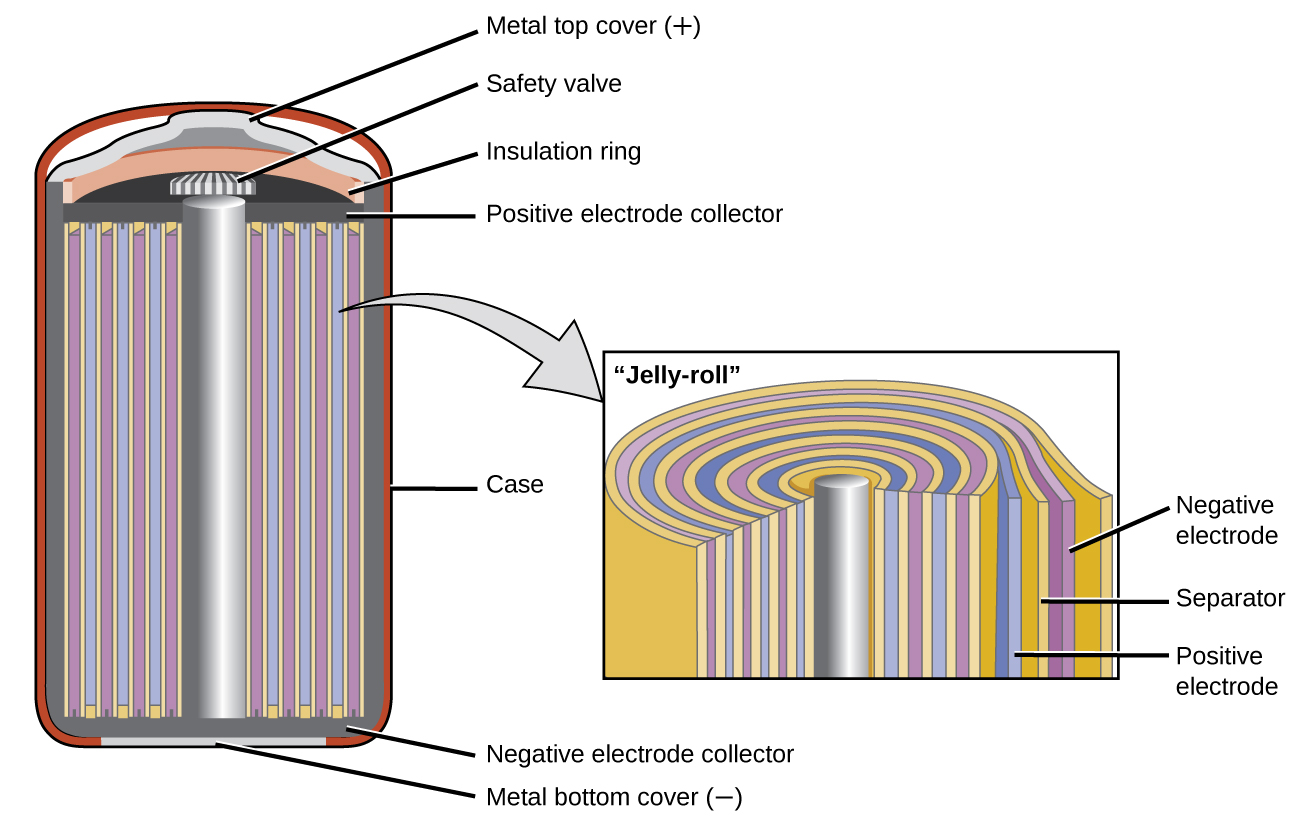
Nickel-cadmium, or NiCd, batteries (Figure 13) consist of a nickel-plated cathode, cadmium-plated anode, and a potassium hydroxide electrode. The positive and negative plates, which are prevented from shorting by the separator, are rolled together and put into the case. This is a “jelly-roll” design and allows the NiCd cell to deliver much more current than a similar-sized alkaline battery. The reactions are:

[latex]\begin{array}{lrcl} \text{anode:} & \text{Cd}(s)\;+\;2\text{OH}^{-}(aq) &\longrightarrow& \text{Cd(OH)}_2(s)\;+\;2\text{e}^{-} \\[0.5em] \text{cathode:} & \text{NiO}_2(s)\;+\;2\text{H}_2\text{O}(l)\;+\;2\text{e}^{-} &\longrightarrow& \text{Ni(OH)}_2(s)\;+\;2\text{OH}^{-}(aq) \\[0.5em] \hline \\[-0.25em] \text{overall:} & \text{Cd}(s)\;+\;\text{NiO}_2(s)\;+\;2\text{H}_2\text{O}(l) &\longrightarrow& \text{Cd(OH)}_2(s)\;+\;\text{Ni(OH)}_2(s) \end{array}[/latex]

The voltage is about 1.25 V to 1.2 V as the battery discharges. When properly treated, a NiCd battery can be recharged about 1000 times. Cadmium is a toxic heavy metal so NiCd batteries should never be opened or put into the regular trash.

A diagram is shown of a cross section of a nickel cadmium battery. This battery is in a cylindrical shape. An outer red layer is labeled “case.” Just inside this layer is a thin, dark grey layer which is labeled at the bottom of the cylinder as “Negative electrode collector.” A silver rod extends upward through the center of the battery, which is surrounded by alternating layers, shown as vertical repeating bands, of yellow, purple, yellow, and blue. A slightly darker grey narrow band extends across the top of these alternating bands, which is labeled “Positive electrode collector.” A thin light grey band appears at the very bottom of the cylinder, which is labeled “Metal bottom cover (negative).” A small grey and white striped rectangular structure is present at the top of the central silver cylinder, which is labeled “Safety valve.” Above this is an orange layer that curves upward over the safety valve, which is labeled “Insulation ring.” Above this is a thin light grey layer that projects upward slightly at the center, which is labeled “Metal top cover (plus).” A light grey arrow points to a rectangle to the right that illustrates the layers at the center of the battery under magnification. From the central silver rod, the layers shown repeat the alternating pattern yellow, blue, yellow, and purple three times, with a final yellow layer covering the last purple layer. The outermost purple layer is labeled “Negative electrode.” The yellow layer beneath it is labeled “Separator.” The blue layer just inside is labeled “Positive electrode.”
Figure 13. NiCd batteries use a “jelly-roll” design that significantly increases the amount of current the battery can deliver as compared to a similar-sized alkaline battery.

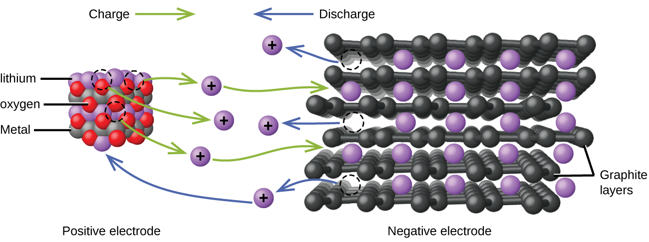
Lithium ion batteries (Figure 14) are among the most popular rechargeable batteries and are used in many portable electronic devices. The reactions are:

[latex]\begin{array}{lrcl} \text{anode:} & \text{LiCoO}_2 &\longrightarrow& \text{Li}_{x\;-\;1}\text{CoO}_2\;+\;x\;\text{Li}^{+}\;+\;x\;\text{e}^{-} \\[0.5em] \text{cathode:} & x\;\text{Li}^{+}\;+\;x\;\text{e}^{-}\;+\;x\;\text{C}_6 &\longrightarrow& x\;\text{LiC}_6 \\[0.5em] \hline \\[-0.25em] \text{overall:} & \text{LiCoO}_2\;+\;x\;\text{C}_6 &\longrightarrow& \text{Li}_{x\;-\;1}\text{CoO}_2\;+\;x\;\text{LiC}_6 \end{array}[/latex]

With the coefficients representing moles, x is no more than about 0.5 moles. The battery voltage is about 3.7 V. Lithium batteries are popular because they can provide a large amount current, are lighter than comparable batteries of other types, produce a nearly constant voltage as they discharge, and only slowly lose their charge when stored.

This figure shows a model of the flow of charge in a lithium ion battery. At the left, an approximately cubic structure formed by alternating red, grey, and purple spheres is labeled below as “Positive electrode.” The purple spheres are identified by the label “lithium.” The grey spheres are identified by the label “Metal.” The red spheres are identified by the label “oxygen.” Above this structure is the label “Charge” followed by a right pointing green arrow. At the right is a figure with layers of black interconnected spheres with purple spheres located in gaps between the layers. The black layers are labeled “Graphite layers.” Below the purple and black structure is the label “Negative electrode.” Above is the label “Discharge,” which is preceded by a blue arrow which points left. At the center of the diagram between the two structures are six purple spheres which are each labeled with a plus symbol. Three curved green arrows extend from the red, purple, and grey structure to each of the three closest purple plus labeled spheres. Green curved arrows extend from the right side of the upper and lower of these three purple plus labeled spheres to the black and purple layered structure. Three blue arrows extend from the purple and black layered structure to the remaining three purple plus labeled spheres at the center of the diagram. The base of each arrow has a circle formed by a dashed curved line in the layered structure. The lowest of the three purple plus marked spheres reached by the blue arrows has a second blue arrow extending from its left side which points to a purple sphere in the purple, green, and grey structure.
Figure 14. In a lithium ion battery, charge flows between the electrodes as the lithium ions move between the anode and cathode.

Ch17.12 Fuel Cells

A fuel cell is a device that converts chemical energy into electrical energy. Fuel cells are similar to batteries but require a continuous source of fuel, often hydrogen. They will continue to produce electricity as long as fuel is available. Hydrogen fuel cells have been used to supply power for satellites, space capsules, automobiles, boats, and submarines (Figure 15).

A diagram is shown of a hydrogen fuel cell. At the center is a narrow vertical rectangle which is shaded tan and labeled “Electrolyte.” To the right is a slightly wider and shorter purple rectangle which is labeled “Cathode.” To the left is a rectangle of the same size which is labeled “Anode.” Grey rectangles that are slightly wider and longer are at the right and left sides, attached to the purple and blue rectangles. On the right side, a white region overlays the grey rectangle. This white region provides a pathway for O subscript 2 to enter at the upper left, move inward and along the interface with the purple region, and exit to the lower right. A similar pathway overlays the grey region on the left, allowing a pathway for the entry of H subscript 2 from the upper right along the interface with the blue rectangle, allowing for the exit of H subscript 2 O out to the lower left of the diagram. Black line segments extend upward from the blue and purple regions. These line segments are connected by a horizontal segment that has a yellow zig zag shape at the center. This shape is labeled “Electric power.” At the left of the diagram, in the upper left white region, 2 H subscript 2 is followed by an arrow that points right and down to H subscript 2. An arrow points right into the blue region to H subscript 2 O. A curved arrow point up to e superscript negative. Another e superscript negative is placed nearby and has an upward pointing arrow extending up to the left of the line segment extending from the purple region. A second arrow points upward along this segment with the label “e superscript negative” to its left. A curved arrow extends down and to the left from the H subscript 2 O into the white region. A second H subscript 2 O is shown below the first in the blue region repeating the arrow patterns established above. At the lower left, an arrow points left, to the exit of the white region. At the tip of this arrow is the label “2 H subscript 2 O.” In the central brown region, O superscript 2 negative is listed twice with arrows pointing left, to the H subscript 2 O formulas in the blue region. At the upper right, O subscript 2 is shown with an arrow pointing left and down to O subscript 2 in the white region. An arrow points left from this point into the purple region. From the tip of the arrow, two arrows point to the two O subscript 2 negative structures in the brown central region. An arrow, labeled “e superscript negative” points downward to the right of the line segment above the purple region. A second arrow extends down into the purple region, pointing to e superscript negative. Three additional e superscript negative symbols appear nearby. An arrow extends from them to the point where the arrows meet in the purple region.
Figure 15. In this hydrogen fuel-cell schematic, oxygen from the air reacts with hydrogen, producing water and electricity.

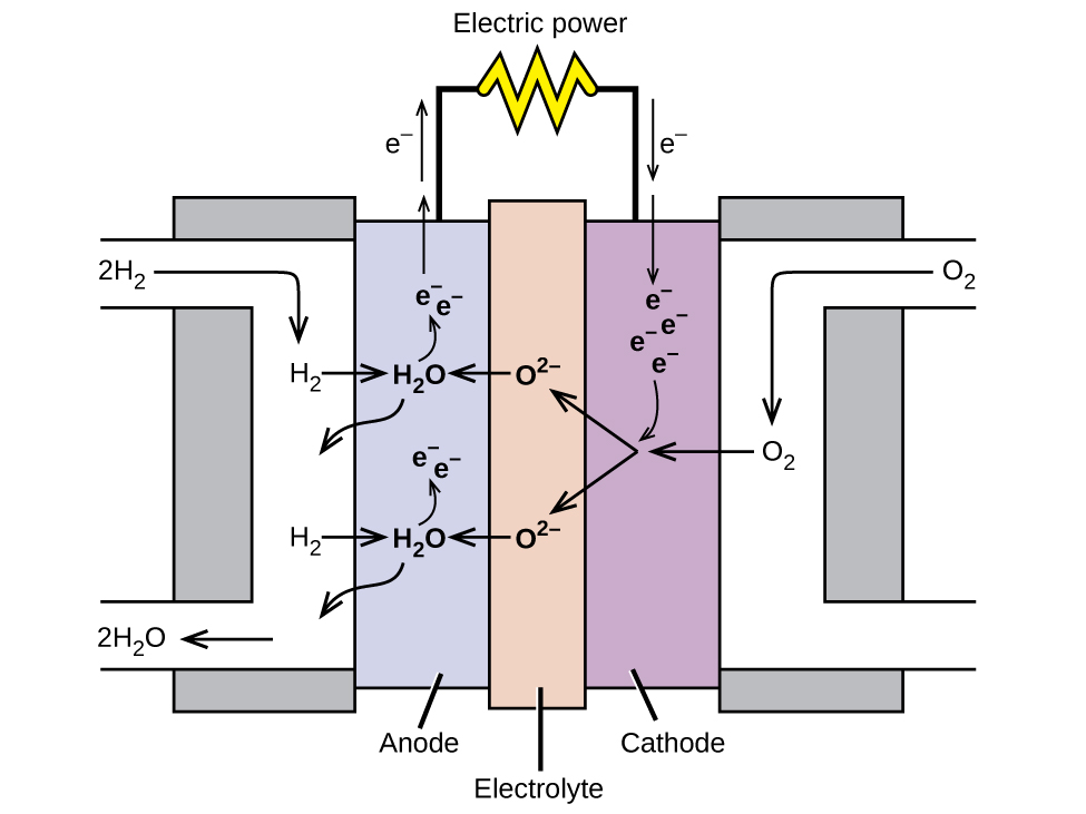
In a hydrogen fuel cell, the reactions are:

[latex]\begin{array}{lrcl} \text{anode:} & 2\text{H}_2\;+\;2\text{O}^{2-} &\longrightarrow& 2\text{H}_2\text{O}\;+\;4\text{e}^{-} \\[0.5em] \text{cathode:} & \text{O}_2\;+\;4\text{e}^{-} &\longrightarrow& 2\text{O}^{2-} \\[0.5em] \hline \\[-0.25em] \text{overall:} & 2\text{H}_2\;+\;\text{O}_2 &\longrightarrow& 2\text{H}_2\text{O} \end{array}[/latex]

The voltage is about 0.9 V. The efficiency of fuel cells is typically about 40-60%, which is higher than the typical internal combustion engine (25-35%) and, in the case of the hydrogen fuel cell, produces only water as exhaust. Currently, fuel cells are rather expensive and contain features that may cause higher failure rate.

Ch17.13 Electrolysis

In galvanic cells, chemical energy is converted into electrical energy. The opposite is true for electrolytic cells, where electrical energy causes nonspontaneous reactions to occur in a process known as electrolysis. The charging a rechargeable battery is such an example, where electrical energy is converted into the chemical energy in the battery as it is charged.

The same principles are involved in electrolytic cells as in galvanic cells. We will look at three electrolytic cells and the quantitative aspects of electrolysis.

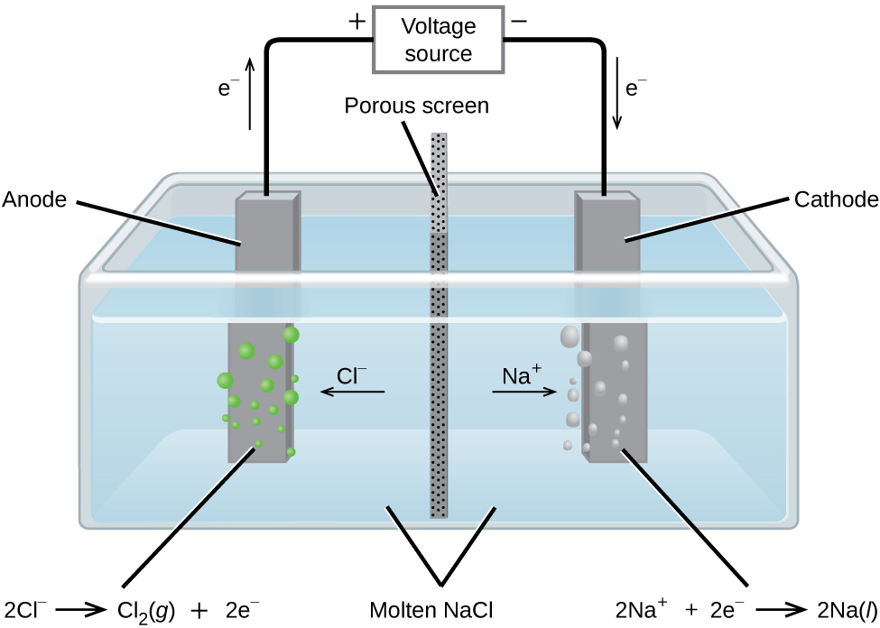
In molten sodium chloride, the ions are free to migrate to the electrodes of an electrolytic cell. A simplified diagram of the cell commercially used to produce sodium metal and chlorine gas is shown in Figure 16. Sodium is a strong reducing agent and chlorine is used to purify water, and is used in antiseptics and in paper production. The reactions are:

[latex]\begin{array}{lrcll} \text{anode:} & 2\text{Cl}^{-}(l) &\longrightarrow& \text{Cl}_2(g)\;+\;2\text{e}^{-} & E_{\text{Cl}_2/\text{Cl}^{-}}^{\circ} = +1.3\;\text{V} \\[0.5em] \text{cathode:} & \text{Na}^{+}(l)\;+\;\text{e}^{-} & \text{Na}(l) &\longrightarrow& E_{\text{Na}^{+}/\text{Na}}^{\circ} = -2.7\;\text{V} \\[0.5em] \hline \\[-0.25em] \text{overall:} & 2\text{Na}^{+}(l)\;+\;2\text{Cl}^{-}(l) &\longrightarrow& 2\text{Na}(l)\;+\;\text{Cl}_2(g) & E_{\text{cell}}^{\circ} = -4.0\;\text{V} \end{array}[/latex]

The power supply (battery) must supply a minimum of 4 V. In practice, the applied voltages are typically higher because of inefficiencies in the process itself.

This diagram shows a tank containing a light blue liquid, labeled “Molten N a C l.” A vertical dark grey divider with small, evenly distributed dark dots, labeled “Porous screen” is located at the center of the tank dividing it into two halves. Dark grey bars are positioned at the center of each of the halves of the tank. The bar on the left, which is labeled “Anode” has green bubbles originating from it. The bar on the right which is labeled “Cathode” has light grey bubbles originating from it. An arrow points left from the center of the tank toward the anode, which is labeled “C l superscript negative.” An arrow points right from the center of the tank toward the cathode, which is labeled “N a superscript plus.” A line extends from the tops of the anode and cathode to a rectangle centrally placed above the tank which is labeled “Voltage source.” An arrow extends upward above the anode to the left of the line which is labeled “e superscript negative.” A plus symbol is located to the left of the voltage source and a negative sign it located to its right. An arrow points downward along the line segment leading to the cathode. This arrow is labeled “e superscript negative.” The left side of below the diagram is the label “2 C l superscript negative right pointing arrow C l subscript 2 ( g ) plus 2 e superscript negative.” At the right, below the diagram is the label “2 N a superscript plus plus 2 e superscript negative right pointing arrow 2 N a ( l ).”
Figure 16. Passing an electric current through molten sodium chloride decomposes the material into sodium metal and chlorine gas. Care must be taken to keep the products separated to prevent the spontaneous formation of sodium chloride.

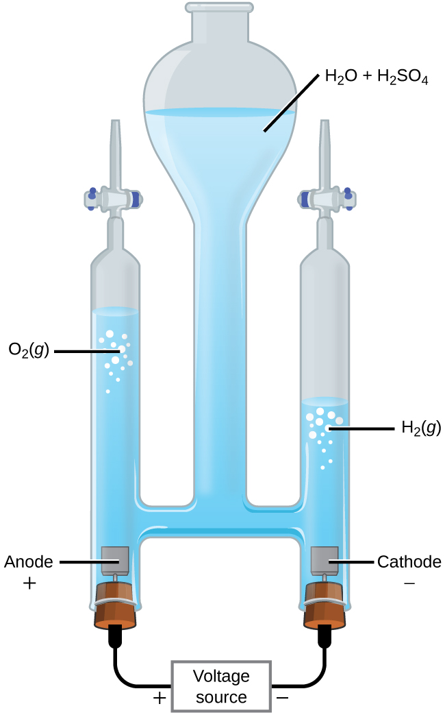
It is possible to split water into hydrogen and oxygen gas by electrolysis. Acids are typically added to increase the concentration of hydrogen ion in solution (Figure 17). The reactions are:

[latex]\begin{array}{lrcll} \text{anode:} & 2\text{H}_2\text{O}(l) &\longrightarrow& \text{O}_2(g)\;+\;4\text{H}^{+}(aq)\;+\;4\text{e}^{-} & E_{\text{anode}}^{\circ} = +1.229\;\text{V} \\[0.5em] \text{cathode:} & 2\text{H}^{+}(aq)\;+\;2\text{e}^{-} &\longrightarrow& \text{H}_2(g) & E_{\text{cathode}}^{\circ} = 0\;\text{V} \\[0.5em] \hline \\[-0.25em] \text{overall:} & 2\text{H}_2\text{O}(l) &\longrightarrow& 2\text{H}_2(g)\;+\;\text{O}_2(g) & E_{\text{cell}}^{\circ} = -1.229\;\text{V} \end{array}[/latex]

Note that the sulfuric acid is not consumed and that the volume of hydrogen gas produced is twice the volume of oxygen gas produced. The minimum applied voltage needed is 1.229 V.

This figure shows an apparatus used for electrolysis. A central chamber with an open top has a vertical column extending below that is nearly full of a clear, colorless liquid, which is labeled “H subscript 2 O plus H subscript 2 S O subscript 4.” A horizontal tube in the apparatus connects the central region to vertical columns to the left and right, each of which has a valve or stopcock at the top and a stoppered bottom. On the left, the stopper at the bottom has a small brown square connected just above it in the liquid. The square is labeled “Anode plus.” A black wire extends from the stopper at the left to a rectangle which is labeled “Voltage source” on to the stopper at the right. The left side of the rectangle is labeled with a plus symbol and the right side is labeled with a negative sign. The stopper on the right also has a brown square connected to it which is in the liquid in the apparatus. This square is labeled “Cathode negative.” The level of the solution on the left arm or tube of the apparatus is significantly higher than the level of the right arm. Bubbles are present near the surface of the liquid on each side of the apparatus, with the bubbles labeled as “O subscript 2 ( g )” on the left and “H subscript 2 ( g )” on the right.
Figure 17. Water decomposes into oxygen and hydrogen gas during electrolysis. Sulfuric acid is added to increase the concentration of hydrogen ions and the total number of ions in solution, but does not take part in the reaction. The volume of hydrogen gas collected is twice the volume of oxygen gas collected, due to the stoichiometry of the reaction.

The electrolysis of aqueous sodium chloride is interesting because more than one species can be oxidized and reduced. Considering the anode first, the possible reactions are:

[latex]\begin{array}{lcll} (\text{i})\;2\text{Cl}^{-}(aq) &\longrightarrow& \text{Cl}_2(g)\;+\;2\text{e}^{-} & E_{\text{anode}}^{\circ} = +1.358\;\text{V} \\[0.5em] (\text{ii})\;2\text{H}_2\text{O}(l) &\longrightarrow& \text{O}_2(g)\;+\;4\text{H}^{+}(aq)\;+\;4\text{e}^{-} & E_{\text{anode}}^{\circ} = +1.229\;\text{V} \end{array}[/latex]

These values suggest that water should be oxidized at the anode because a smaller potential would be needed—using reaction (ii) for the oxidation would give a less-negative cell potential. When the experiment is run, it turns out chlorine, not oxygen, is produced at the anode. This unexpected result is quite common in electrochemistry, and is caused by the overpotential of the reaction. The overpotential is the difference between the theoretical cell voltage and the actual voltage that is necessary to cause electrolysis. It turns out that the overpotential for oxygen is rather high and effectively makes the reduction potential more positive. As a result, under normal conditions, chlorine gas is what actually forms at the anode.

Now consider the cathode. Three reductions can occur:

[latex]\begin{array}{lcll} (\text{iii})\;2\text{H}^{+}(aq)\;+\;2\text{e}^{-} &\longrightarrow& \text{H}_2(g) & E_{\text{cathode}}^{\circ} = 0\;\text{V} \\[0.5em] (\text{iv})\;2\text{H}_2\text{O}(l)\;+\;2\text{e}^{-} &\longrightarrow& \text{H}_2(g)\;+\;2\text{OH}^{-}(aq) & E_{\text{cathode}}^{\circ} = -0.8277\;\text{V} \\[0.5em] (\text{v})\;\text{Na}^{+}(aq)\;+\;\text{e}^{-} &\longrightarrow& \text{Na}(s) & E_{\text{cathode}}^{\circ} = -2.71\;\text{V} \end{array}[/latex]

Reaction (v) is ruled out because it has such a negative reduction potential. Under standard state conditions, reaction (iii) would be preferred to reaction (iv). However, the pH of a sodium chloride solution is 7, so the concentration of hydrogen ions is only 1× 10⁻⁷M. At such low concentrations, reaction (iii) is unlikely and reaction (iv) occurs. The overall reaction is then:

[latex]2\text{H}_2\text{O}(l)\;+\;2\text{Cl}^{-}(aq)\;{\longrightarrow}\;\text{H}_2(g)\;+\;\text{Cl}_2(g)\;+\;2\text{OH}^{-}(aq)\;\;\;\;\;\;\;E_{\text{cell}}^{\circ} = -2.186\;\text{V}[/latex]

As the reaction proceeds, hydroxide ions replace chloride ions in solution. Thus, sodium hydroxide can be obtained by evaporating the water after the electrolysis is complete. Sodium hydroxide is valuable in its own right and is used for things like oven cleaner, drain opener, and in the production of paper, fabrics, and soap.

Electroplating

An important use for electrolytic cells is electroplating. Electroplating results in a thin coating of one metal on top of a conducting surface. Reasons for electroplating include making the object more corrosion resistant, strengthening the surface, producing a more attractive finish, or for purifying metal. The metals commonly used in electroplating include cadmium, chromium, copper, gold, nickel, silver, and tin. Common consumer products include silver-plated or gold-plated tableware, chrome-plated automobile parts, and jewelry. We can get an idea of how this works by investigating how silver-plated tableware is produced (Figure 18).

This figure contains a diagram of an electrochemical cell. One beakers is shown that is just over half full. The beaker contains a clear, colorless solution that is labeled “A g N O subscript 3 ( a q ).” A silver strip is mostly submerged in the liquid on the left. This strip is labeled “Silver (anode).” The top of the strip is labeled with a red plus symbol. An arrow points right from the surface of the metal strip into the solution to the label “A g superscript plus” to the right. A spoon is similarly suspended in the solution and is labeled “Spoon (cathode).” It is labeled with a black negative sign on the tip of the spoon’s handle above the surface of the liquid. An arrow extends from the label “A g superscript plus” to the spoon on the right. A wire extends from the top of the spoon and the strip to a rectangle labeled “Voltage source.” An arrow points upward from silver strip which is labeled “e superscript negative.” Similarly, an arrow points down at the right to the surface of the spoon which is also labeled “e superscript negative.” A plus sign is shown just outside the voltage source to the left and a negative is shown to its right.
Figure 18. The spoon, which is made of an inexpensive metal, is connected to the negative terminal of the voltage source and acts as the cathode. The anode is a silver electrode. Both electrodes are immersed in a silver nitrate solution. When a steady current is passed through the solution, the net result is that silver metal is removed from the anode and deposited on the cathode.

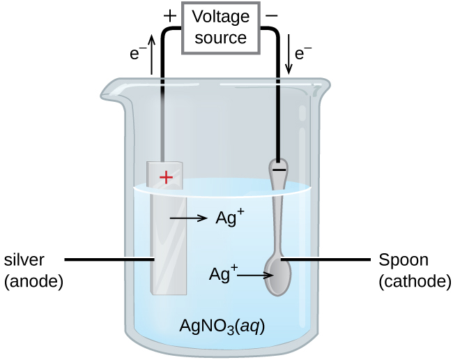
In the figure, the anode consists of a silver electrode, shown on the left. The cathode is located on the right and is the spoon, which is made from an inexpensive metal. Both electrodes are immersed in a solution of silver nitrate. As the potential is increased, current flows. Silver metal is lost at the anode as it goes into solution:

[latex]\text{anode:}\;\text{Ag}(s)\;{\longrightarrow}\;\text{Ag}^{+}(aq)\;+\;\text{e}^{-}[/latex]

The mass of the cathode increases as silver ions from the solution are deposited onto the spoon:

[latex]\text{cathode:}\;\text{Ag}^{+}(aq)\;+\;\text{e}^{-}\;{\longrightarrow}\;\text{Ag}(s)[/latex]

The net result is the transfer of silver metal from the anode to the cathode. The quality of the object is usually determined by the thickness of the deposited silver and the rate of deposition.

Ch17.14 Quantitative Aspects of Electrolysis

The amount of current that is allowed to flow in an electrolytic cell is related to the number of moles of electrons. The number of moles of electrons can be related to the reactants and products using stoichiometry. Recall that the SI unit for current (I) is the ampere (A), which is the equivalent of 1 coulomb per second (1 A = 1 [latex]\frac{\text{C}}{\text{s}}[/latex]). The total charge (Q, in coulombs) is given by:

[latex]Q = I\;\times\;t = n\;\times\;F[/latex]

where t is the time in seconds, n the number of moles of electrons, and F is the Faraday constant.

Example 10

Converting Current to Moles of Electrons
In one process used for electroplating silver, a current of 10.23 A was passed through an electrolytic cell for exactly 1 hour. How many moles of electrons passed through the cell? What mass of silver was deposited at the cathode from the silver nitrate solution?

Solution
Faraday’s constant can be used to convert the charge (Q) into moles of electrons (n). The charge is the current (I) multiplied by the time:

[latex]n = \frac{Q}{F} = \frac{(10.23\;\text{C/s})\;(1\;\text{hr})\;(60\;\text{min/hr})\;(60\;\text{s/min})}{96,485\;\text{C/mol e}^{-}} = \frac{36,830\;\text{C}}{96,485\;\text{C/mol e}^{-}} = 0.3817\;\text{mol e}^{-}[/latex]

The electroplating solution contains AgNO3, so the reaction at the cathode involves 1 mole of electrons for each mole of silver:

[latex]\text{cathode:}\;\text{Ag}^{+}(aq)\;+\;\text{e}^{-}\;{\longrightarrow}\;\text{Ag}(s)[/latex]

The atomic mass of silver is 107.9 g/mol, so:

[latex]\text{mass Ag deposited} = 0.3817\;\text{mol e}^{-}\;\times\;\frac{1\;\text{mol Ag}}{1\;\text{mol e}^{-}}\;\times\;\frac{107.9\;\text{g Ag}}{1\;\text{mol Ag}} = 41.19\;\text{g Ag}[/latex]

Check your answer: From the stoichiometry, 1 mole of electrons would produce 1 mole of silver. Less than one-half a mole of electrons was involved and less than one-half a mole of silver was produced.

Check Your Learning
Aluminum metal can be made from aluminum ions by electrolysis. What is the half-reaction at the cathode? What mass of aluminum metal would be recovered if a current of 2.50 × 10³ A passed through the solution for 15.0 minutes? Assume the yield is 100%.

Answer:

[latex]\text{Al}^{3+}(aq)\;+\;3\text{e}^{-}\;{\longrightarrow}\;\text{Al}(s)[/latex]; 7.77 mol Al = 210. g Al.

Example 11

Time Required for Deposition
In one application, a 0.010-mm layer of chromium must be deposited on a part with a total surface area of 3.3 m2 from a solution containing chromium(III) ions. How long would it take to deposit the layer of chromium if the current is 33.46 A? The density of chromium (metal) is 7.19 g/cm3.

Solution
This problem brings in a number of topics covered earlier. An outline of what needs to be done is:

  • If the total charge can be determined, the time required is just the charge divided by the current
  • The total charge can be obtained from the amount of Cr needed and the reaction stoichiometry
  • The amount of Cr can be obtained using the density and the volume of Cr required
  • The volume Cr required is the thickness times the area

Solving in steps, and taking care with the units, the volume of Cr required is:

[latex]\text{volume} = (0.010\;\text{mm}\;\times\;\frac{1\;\text{cm}}{10\;\text{mm}})\;\times\;(3.3\;\text{m}^2\;\times\;(\frac{10,000\;\text{cm}^2}{1\;\text{m}^2})) = 33\;\text{cm}^{3}[/latex]

Cubic centimeters unit matches the volume unit used for the density. The amount of Cr is then:

[latex]\text{mass} = \text{volume}\;\times\;\text{density} = 33\;\rule[0.6ex]{1.75em}{0.1ex}\hspace{-1.75em}\text{cm}^3\;\times\;\frac{7.19\;\text{g}}{\rule[0.25ex]{1.15em}{0.1ex}\hspace{-1.15em}\text{cm}^{3}} = 237\;\text{g\;Cr}[/latex]
[latex]\text{mol Cr} = 237\;\text{g Cr}\;\times\;\frac{1\;\text{mol Cr}}{52.00\;\text{g Cr}} = 4.56\;\text{mol Cr}[/latex]

Since the solution contains chromium(III) ions (Cr3+), 3 moles of electrons are required per mole of Cr. The total charge is then:

[latex]Q = 4.56\;\text{mol Cr}\;\times\;\frac{3\;\text{mol e}^{-}}{1\;\text{mol Cr}}\;\times\;\frac{96485\;\text{C}}{\text{mol e}^{-}} = 1.32\;\times\;10^6\;\text{C}[/latex]

The time required is then:

[latex]t = \frac{Q}{I} = \frac{1.32\;\times\;10^6\;\text{C}}{33.46\;\text{C/s}} = 3.95\;\times\;10^4\;\text{s} = 11.0\;\text{hr}[/latex]

Check your answer: In a long problem like this, a single check is probably not enough. Each of the steps gives a reasonable number, so things are probably correct. Pay careful attention to unit conversions and the stoichiometry.

License

Icon for the Creative Commons Attribution-NonCommercial-ShareAlike 4.0 International License

Chemistry 109 Copyright © by John Moore; Jia Zhou; and Etienne Garand is licensed under a Creative Commons Attribution-NonCommercial-ShareAlike 4.0 International License, except where otherwise noted.