Unit Four

Day 41: Concentration Cells; Batteries

As you work through this section, if you find that you need a bit more background material to help you understand the topics at hand, you can consult “Chemistry: The Molecular Science” (5th ed. Moore and Stanitski) Chapter 17-8 and 17-9, and/or Chapter 17.8-17.11 in the Additional Reading Materials section.

D41.1 Concentration Cells

A concentration cell is a special type of voltaic cell where the electrodes are the same material but the half-cells have different concentrations of soluble species. Because one or both half-cells does not involve standard-state conditions, the half-cell potentials are unequal. Therefore, there is a potential difference between the half-cells. That potential difference can be calculated using the Nernst equation.

For example, consider this cell:

Zn(s) | Zn2+(aq, 0.10 M) || Zn2+(aq, 0.50 M) | Zn(s)

The standard cell potential is 0 V because the anode and cathode involve the same reaction; however, the process is spontaneous because if equal volumes of the two half-cell solutions were mixed, the concentration of Zn2+ would change to the average of the initial concentrations, namely, to 0.30 M. The cell can do work because the concentrations of Zn2+ change.

[latex]\begin{array}{lrcll} \text{Anode:} & \text{Zn}(\text{s}) &\longrightarrow& \text{Zn}^{2+}(\text{aq},\;0.10\;\text{M})\;+\;2\text{e}^{-} & E_{\text{anode}}^{\circ} = -0.763\;\text{V} \\[0.5em] \text{Cathode:} & \text{Zn}^{2+}(\text{aq},\;0.50\;\text{M})\;+\;2\text{e}^{-} &\longrightarrow& \text{Zn}(\text{s}) & E_{\text{cathode}}^{\circ} = -0.763\;\text{V} \\[0.5em] \hline \\[-0.25em] \text{Overall:} & \text{Zn}^{2+}(\text{aq},\;0.50\;\text{M}) &\longrightarrow& \text{Zn}^{2+}(\text{aq},\;0.10\;\text{M}) & E_{\text{cell}}^{\circ} = 0.000\;\text{V} \end{array}[/latex]

The Nernst equation verifies that the process is spontaneous at the given conditions, and Ecell > 0 V:

[latex]E_{\text{cell}} = 0.000\;\text{V}\;-\;\dfrac{(8.314\;\text{J}/\text{K}{\cdot}\text{mol})(298\;\text{K})}{(2)(96485\;\text{J}/\text{V}{\cdot}\text{mol})}\;\text{ln}\left(\dfrac{0.10\;\text{M}}{0.50\;\text{M}}\right) = +0.021\;\text{V}[/latex]

In a concentration cell, the standard cell potential is always zero. To get a positive cell potential (spontaneous process) the reaction quotient Q must be < 1. As the reaction proceeds, Q approaches 1 and Ecell approaches 0 V.

D41.2 Batteries

A battery is an electrochemical cell or series of cells that produces an electric current. In principle, any voltaic cell can be used as a battery. An ideal battery would never run down, produce an unchanging voltage, and be capable of withstanding environmental extremes of heat and humidity. Real batteries strike a balance between ideal characteristics and practical limitations.

For example, the mass of a car battery is about 18 kg or ~1% of the mass of an average car. This type of battery would supply nearly unlimited energy if used in a smartphone, but would be completely impractical because of its mass. Thus, no single battery is “best” and batteries are selected for a particular application, keeping things like its mass, cost, reliability, and current capacity in mind.

There are two basic types of batteries: primary and secondary. A few batteries of each type are described next.

D41.3 Primary Batteries

Primary batteries are single-use batteries that cannot be recharged. A common primary battery is the dry cell (Figure 1), which is a zinc-carbon battery. The zinc serves as both a container and the negative electrode. The positive electrode is a rod made of carbon that is surrounded by a paste of manganese(IV) oxide, zinc chloride, ammonium chloride, carbon powder, and a small quantity of water.

A diagram of a cross section of a dry cell battery is shown. The overall shape of the cell is cylindrical. The lateral surface of the cylinder, indicated as a thin red line, is labeled “zinc can (electrode).” Just beneath this is a slightly thicker dark grey surface that covers the lateral surface, top, and bottom of the battery, which is labeled “Porous separator.” Inside is a purple region with many evenly spaced small darker purple dots, labeled “Paste of M n O subscript 2, N H subscript 4 C l, Z n C l subscript 2, water (cathode).” A dark grey rod, labeled “Carbon rod (electrode),” extends from the top of the battery, leaving a gap of less than one-fifth the height of the battery below the rod to the bottom of the cylinder. A thin grey line segment at the very bottom of the cylinder is labeled “Metal bottom cover (negative).” The very top of the cylinder has a thin grey surface that curves upward at the center over the top of the carbon electrode at the center of the cylinder. This upper surface is labeled “Metal top cover (positive).” A thin dark grey line just below this surface is labeled “Insulator.” Below this, above the purple region, and outside of the carbon electrode at the center is an orange region that is labeled “Seal.”
Figure 1. A cross section of a flashlight battery, a zinc-carbon dry cell.

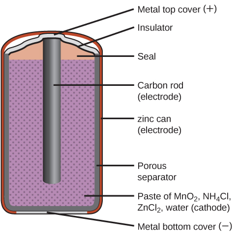
The reaction at the anode can be represented as the ordinary oxidation of zinc:

Zn(s) ⟶ Zn2+(aq) + 2 e¯     E° = -0.763 V

The reaction at the cathode is more complicated, in part because more than one reduction reaction occurs. The series of reactions that occurs at the cathode is approximately:

2 MnO2(s) + 2 NH4Cl(aq) + 2e¯ ⟶ Mn2O3(s) + 2 NH3(aq) + H2O(l) + 2 Cl¯(aq)

The overall reaction for the zinc–carbon battery can be represented as:

2 MnO2(s) + 2 NH4Cl(aq) + Zn(s) ⟶ Mn2O3(s) + 2 NH3(aq) + H2O(l) + 2 Cl¯(aq) + Zn2+(aq)

The cell potential is about 1.5 V initially, and decreases as the battery is used. As the zinc container oxidizes, its contents eventually leak out, so this type of battery should not be left in any electrical device for extended periods.

The voltage delivered by a battery is the same regardless of the size of a battery. For this reason, D, C, A, AA, and AAA batteries all have the same voltage. However, larger batteries can deliver more moles of electrons and will therefore last longer if powering the same device.

Alkaline batteries (Figure 2) were developed in the 1950s partly to address some of the performance issues with zinc–carbon dry cells, and are manufactured to be their exact replacements. As their name suggests, these types of batteries use alkaline electrolytes, often potassium hydroxide. The reactions are:

[latex]\begin{array}{lrcll} \text{anode:} & \text{Zn}(\text{s})\;+\;2\;\text{OH}^{-}(\text{aq}) &\longrightarrow& \text{ZnO}(\text{s})\;+\;\text{H}_2\text{O}(l)\;+\;2\;\text{e}^{-} & E_{\text{anode}}^{\circ} = -1.28\;\text{V} \\[0.5em] \text{cathode:} & 2\;\text{MnO}_2(\text{s})\;+\;\text{H}_2\text{O}(l)\;+\;2\;\text{e}^{-} &\longrightarrow& \text{Mn}_2\text{O}_3(\text{s})\;+\;2\;\text{OH}^{-}(\text{aq}) & E_{\text{cathode}}^{\circ} = +0.15\;\text{V} \\[0.5em] \hline \\[-0.25em] \text{overall:} & \text{Zn}(\text{s})\;+\;2\;\text{MnO}_2(\text{s}) &\longrightarrow& \text{ZnO}(\text{s})\;+\;\text{Mn}_2\text{O}_3(\text{s}) & E_{\text{cell}}^{\circ} = +1.43\;\text{V} \end{array}[/latex]
A diagram of a cross section of an alkaline battery is shown. The overall shape of the cell is cylindrical. The lateral surface of the cylinder, indicated as a thin red line, is labeled “Outer casing.” Just beneath this is a thin, light grey surface that covers the lateral surface and top of the battery. Inside is a blue region with many evenly spaced small darker dots, labeled “M n O subscript 2 (cathode).” A thin dark grey layer is just inside, which is labeled “Ion conducting separator.” A purple region with many evenly spaced small darker dots fills the center of the battery and is labeled “ zinc (anode).” The very top of the battery has a thin grey curved surface over the central purple region. The curved surface above is labeled “Positive connection (plus).” At the base of the battery, an orange structure, labeled “Protective cap,” is located beneath the purple and blue central regions. This structure holds a grey structure that looks like a nail with its head at the bottom and pointed end extending upward into the center of the battery. This nail-like structure is labeled “Current pick up.” At the very bottom of the battery is a thin grey surface that is held by the protective cap. This surface is labeled “Negative terminal (negative).”
Figure 2. Alkaline batteries were designed as direct replacements for zinc-carbon (dry cell) batteries.

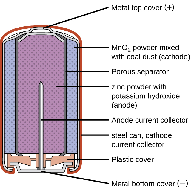
An alkaline battery can deliver about three to five times the energy of a zinc-carbon dry cell of similar size. Alkaline batteries sometimes leak potassium hydroxide, so these should also be removed from devices for long-term storage. While some alkaline batteries are rechargeable, most are not. Attempts to recharge an alkaline battery that is not rechargeable often leads to rupture of the battery and leakage of the potassium hydroxide electrolyte.

D41.4 Lead-Acid Batteries

Secondary batteries are rechargeable; that is, the reaction that powers the battery can be reversed so that the original reactants can be regenerated. Secondary batteries are found in smartphones, electronic tablets, automobiles, and many other devices.

The lead-acid battery (Figure 3) is the type of secondary battery used to start automobiles. It is inexpensive and capable of producing the high current required by the starter motors. The reactions for a lead acid battery are:

[latex]\begin{array}{lrcl} \text{anode:} & \text{Pb}(\text{s})\;+\;\text{HSO}_4^{\;-}(\text{aq}) &\longrightarrow& \text{PbSO}_4(\text{s})\;+\;\text{H}^{+}(aq)\;+\;2\text{e}^{-} \\[0.5em] \text{cathode:} & \text{PbO}_2(\text{s})\;+\;\text{HSO}_4^{\;-}(\text{aq})\;+\;3\text{H}^{+}(\text{aq})\;+\;2\text{e}^{-} &\longrightarrow& \text{PbSO}_4(\text{s})\;+\;2\text{H}_2\text{O}(l) \\[0.5em] \hline \\[-0.25em] \text{overall:} & \text{Pb}(\text{s})\;+\;\text{PbO}_2(\text{s})\;+\;2\text{H}_2\text{SO}_4(\text{aq}) &\longrightarrow& 2\text{PbSO}_4(\text{s})\;+\;2\text{H}_2\text{O}(l) \end{array}[/latex]

Each cell produces 2 V, so six cells can be connected in series to produce a 12-V car battery.

A diagram of a lead acid battery is shown. A black outer casing, which is labeled “Protective casing” is in the form of a rectangular prism. Grey cylindrical projections extend upward from the upper surface of the battery in the back left and back right corners. At the back right corner, the projection is labeled “Positive terminal.” At the back right corner, the projection is labeled “Negative terminal.” The bottom layer of the battery diagram is a dark green color, which is labeled “Dilute H subscript 2 S O subscript 4.” A blue outer covering extends upward from this region near the top of the battery. Inside, alternating grey and white vertical “sheets” are packed together in repeating units within the battery. The battery has the sides cut away to show three of these repeating units which are separated by black vertical dividers, which are labeled as “cell dividers.” The grey layers in the repeating units are labeled “Negative electrode (lead).” The white layers are labeled “Postive electrode (lead dioxide).”
Figure 3. The lead acid battery in an automobile consists of six cells connected in series to give 12 V. The low cost and high current output makes the battery suitable for providing power for a car’s starter motor.

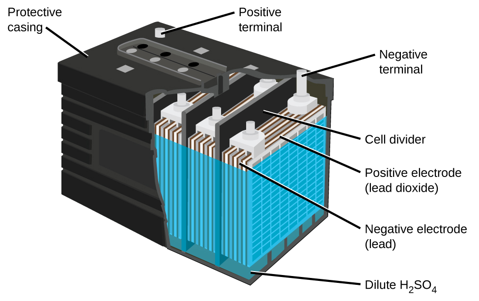
Lead-acid batteries are heavy because of lead’s high density, they contain highly corrosive concentrated sulfuric acid, and must be disposed of properly to avoid lead-poisoning hazards, but they can produce a lot of current in a short time so for certain applications they are the best choice.

Exercise 1: Advantages of Lead-acid Batteries

D41.5 Lithium Ion Batteries

Lithium ion batteries (Figure 1) are among the most popular rechargeable batteries and are used in many portable electronic devices. The reactions are:

[latex]\begin{array}{lrcl} \text{anode:} & \text{LiCoO}_2 &\longrightarrow& \text{Li}_{(1-x)}\text{CoO}_2\;+\;x\;\text{Li}^{+}\;+\;x\;\text{e}^{-} \\[0.5em] \text{cathode:} & x\;\text{Li}^{+}\;+\;x\;\text{e}^{-}\;+\;x\;\text{C}_6 &\longrightarrow& x\;\text{LiC}_6 \\[0.5em] \hline \\[-0.25em] \text{overall:} & \text{LiCoO}_2\;+\;x\;\text{C}_6 &\longrightarrow& \text{Li}_{x\;-\;1}\text{CoO}_2\;+\;x\;\text{LiC}_6 \end{array}[/latex]

(x is no more than about 0.5 moles.) The battery voltage is about 3.7 V.

This figure shows a model of the flow of charge in a lithium ion battery. At the left, an approximately cubic structure formed by alternating red, grey, and purple spheres is labeled below as “Positive electrode.” The purple spheres are identified by the label “lithium.” The grey spheres are identified by the label “Metal.” The red spheres are identified by the label “oxygen.” Above this structure is the label “Charge” followed by a right pointing green arrow. At the right is a figure with layers of black interconnected spheres with purple spheres located in gaps between the layers. The black layers are labeled “Graphite layers.” Below the purple and black structure is the label “Negative electrode.” Above is the label “Discharge,” which is preceded by a blue arrow which points left. At the center of the diagram between the two structures are six purple spheres which are each labeled with a plus symbol. Three curved green arrows extend from the red, purple, and grey structure to each of the three closest purple plus labeled spheres. Green curved arrows extend from the right side of the upper and lower of these three purple plus labeled spheres to the black and purple layered structure. Three blue arrows extend from the purple and black layered structure to the remaining three purple plus labeled spheres at the center of the diagram. The base of each arrow has a circle formed by a dashed curved line in the layered structure. The lowest of the three purple plus marked spheres reached by the blue arrows has a second blue arrow extending from its left side which points to a purple sphere in the purple, green, and grey structure.
Figure 4. In a lithium ion battery, charge flows between the electrodes as the lithium ions move between the anode and cathode.

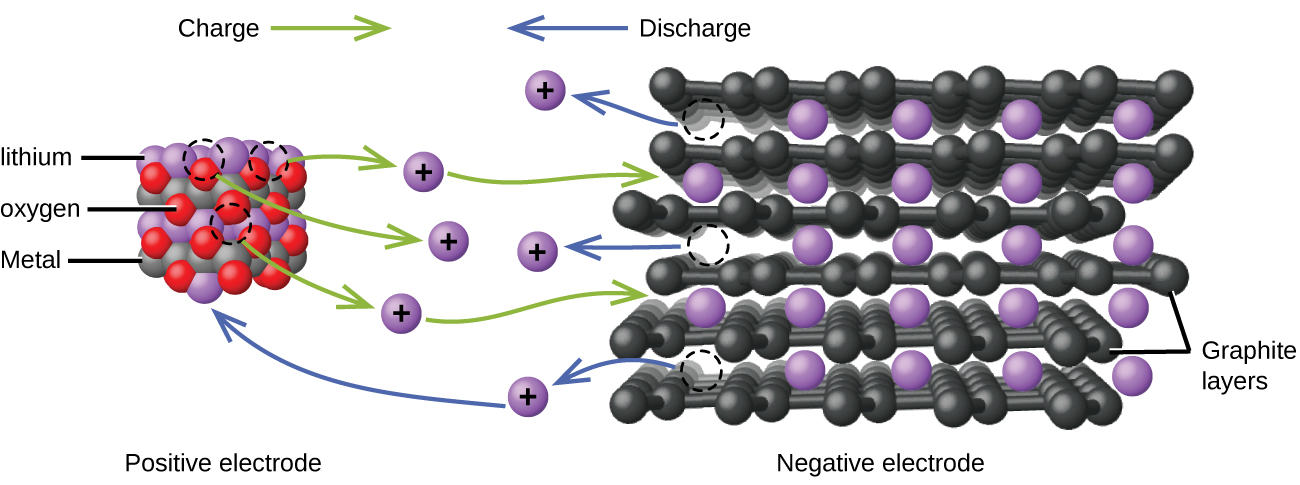
Lithium batteries are popular because they can provide a large amount of current, are lighter than comparable batteries of other types, produce a nearly constant voltage as they discharge, and only slowly lose their charge when stored.

Exercise 2: Lithium-Ion Batteries

Podia Question

Concentration cells are described in Section D41.1 above. A concentration cell is made at 25 °C by placing a Zn electrode at the bottom of a beaker, running an insulated wire from the electrode to the top of the beaker, and covering the electrode with 500. mL 0.50-M ZnSO4(aq). A piece of filter paper the same diameter as the beaker is floated on the 0.50-M ZnSO4 solution, 500. mL of a less concentrated ZnSO4 solution is poured carefully onto the filter paper (so that the two solutions do not mix), and a Zn electrode is suspended in the upper solution. The cell generates 0.10 V.  Calculate the concentration of the second solution.

Two days before the next whole-class session, this Podia question will become live on Podia, where you can submit your answer.

License

Icon for the Creative Commons Attribution-NonCommercial-ShareAlike 4.0 International License

Chemistry 109 Copyright © by John Moore; Jia Zhou; and Etienne Garand is licensed under a Creative Commons Attribution-NonCommercial-ShareAlike 4.0 International License, except where otherwise noted.