Unit Four

Day 42: Electrolysis

As you work through this section, if you find that you need a bit more background material to help you understand the topics at hand, you can consult “Chemistry: The Molecular Science” (5th ed. Moore and Stanitski) Chapter 17-10 through 17-11, and/or Chapter 17.11-17.14 in the Additional Reading Materials section.

D42.1 Fuel Cells

Suppose a voltaic cell was constructed so that the substance that was oxidized at the anode and the substance that was reduced at the cathode (the reactants in the overall cell reaction) were both supplied continuously. The battery would never run down because reactant concentrations or partial pressures would never decrease. Such a device is a fuel cell. A fuel cell produces electricity as long as fuel is available. Hydrogen fuel cells have been used to supply power for satellites, space capsules, automobiles, boats, and submarines (Figure 1).

A diagram is shown of a hydrogen fuel cell. At the center is a narrow vertical rectangle which is shaded tan and labeled “Electrolyte.” To the right is a slightly wider and shorter green rectangle which is labeled “Cathode.” To the left is a pale blue rectangle of the same size which is labeled “Anode.” White rectangles, each with an inlet at the top and an outlet at the bottom are at the right and left sides, attached to the green and blue rectangles. On the right side O subscript 2 enters at the top, moves inward and along the interface with the green region, and exits to the lower right. H subscript 2 O also exits at the lower right. Pale gray diatomic O subscript 2 molecules move through this region and at the bottom are converted to a single pale gray atom with two smaller bright red atoms, H 2 O molecules. A similar pathway is on the left, allowing entry of H subscript 2 from the upper left along the interface with the blue rectangle, allowing for the exit of H subscript 2 out to the lower left of the diagram. Small red diatomic H subscript 2 molecules ar shown in this region. Black line segments extend upward from the blue anode and purple cathode regions. These line segments are connected by a horizontal segment that has a yellow light-bulb shape at the center. H subscript 2 molecules travel into the anode where they lose electrons and become single, small, red circles labeled H superscript plus. H superscript plus ions are shown traveling though the electrolyte to the green cathode where they interact with O subscript 2 molecules to form water molecules. The electrolyte is a special membrane permeable to H superscript plus but not to electrons.
Figure 1. In this schematic of a hydrogen-oxygen proton-exchange fuel cell, oxygen from the air reacts with hydrogen, producing water and electricity.

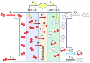
In a hydrogen-oxygen proton-exchangefuel cell, the reactions are:

[latex]\begin{array}{lrcl} \text{anode:} & 2\;\text{H}_2(\text{g})\; &\longrightarrow& 2\;\text{H}^+(\text{aq})\;+\;2\;\text{e}^{-} \\[0.5em] \text{cathode:} & \text{O}_2(\text{g})\;+\;4\text{H}^{+}(\text{aq})\;+\;4\text{e}^{-} &\longrightarrow& 2\;\text{H}_2\text{O}(l) \\[0.5em] \hline \\[-0.25em] \text{overall:} & 2\;\text{H}_2(\text{g})\;+\;\text{O}_2(\text{g}) &\longrightarrow& 2\;\text{H}_2\text{O}(l) \end{array}[/latex]

The cell potential is about 1 V.

The efficiency of fuel cells is typically about 40-60%, which is higher than the typical internal combustion engine (25-35%) and, in the case of the hydrogen fuel cell, produces only water as exhaust. Currently, fuel cells are rather expensive and contain features that may cause a higher failure rate.

D42.2 Electrolysis

In an electrolytic cell electrical energy causes a nonspontaneous reaction to occur in a process known as electrolysis. An electrolytic cell is the opposite of a voltaic cell, where a spontaneous chemical reaction produces electrical energy. Charging a rechargeable battery is an example of electrolysis: electrical energy causes a chemical reaction in the battery, replenishing substances that reacted away as the battery discharged (produced electricity).

For example, consider electrolysis of molten sodium chloride. A simplified diagram of the electrolytic cell used for commercial manufacture of sodium metal and chlorine gas is shown in Figure 2. An external source of direct electric current forces electrons to move into the electrode in the cathode half-cell compartment. The electrons cause reduction of sodium ions to sodium atoms (reduction occurs at the cathode). In the molten salt, sodium ions move toward the cathode and chloride ions move toward the anode (note that negative ions move through the circuit in the same direction as electrons). In the anode half-cell, each chloride ion loses one electron to the electrode surface and oxidation to chlorine gas takes place (oxidation occurs at the anode). The electrons are conducted through a wire to the the voltage source, completing the electric circuit. A porous screen allows movement of ions but not mixing of sodium metal and chlorine gas, which would react spontaneously upon contact.
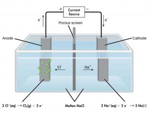
This diagram shows a tank containing a light blue liquid, labeled “Molten N a C l.” A vertical dark grey divider with small, evenly distributed dark dots, labeled “Porous screen” is located at the center of the tank dividing it into two halves. Dark grey bars are positioned at the center of each of the halves of the tank. The bar on the left, which is labeled “Anode” has green bubbles originating from it. The bar on the right which is labeled “Cathode” has no bubbles originating from it. An arrow points left from the center of the tank toward the anode, which is labeled “C l superscript negative.” An arrow points right from the center of the tank toward the cathode, which is labeled “N a superscript plus.” A line extends from the tops of the anode and cathode to a rectangle centrally placed above the tank which is labeled “Current source.” An arrow extends upward above the anode to the left of the line which is labeled “e superscript negative.” A plus symbol is located to the left of the current source and a negative sign is located to its right. An arrow points downward along the line segment leading to the cathode. This arrow is labeled “e superscript negative.” Below the left side of the diagram is the label “2 C l superscript negative ( a q ) right pointing arrow C l subscript 2 ( g ) plus 2 e superscript negative.” At the right, below the diagram is the label “2 N a superscript positive ( a q ) plus 2 e superscript negative right pointing arrow 2 N a ( l ).”
Figure 2. Passing an electric current through NaCl(l) decomposes the molten salt into sodium metal and chlorine gas. Care must be taken to keep the products separated to prevent the spontaneous re-formation of sodium chloride.

The reactions are:

[latex]\begin{array}{lrcll} \text{anode:} & 2\;\text{Cl}^{-}(l) &\longrightarrow& \text{Cl}_2(\text{g})\;+\;2\;\text{e}^{-} & E_{\text{Cl}_2|\text{Cl}^{-}}^{\circ} = +1.3\;\text{V} \\[0.5em] \text{cathode:} & \text{Na}^{+}(l)\;+\;\text{e}^{-} &\longrightarrow& \text{Na}(l) & E_{\text{Na}^{+}|\text{Na}}^{\circ} = -2.7\;\text{V} \\[0.5em] \hline \\[-0.25em] \text{overall:} & 2\;\text{Na}^{+}(l)\;+\;2\;\text{Cl}^{-}(l) &\longrightarrow& 2\;\text{Na}(l)\;+\;\text{Cl}_2(\text{g}) & E_{\text{cell}}^{\circ} = -4.0\;\text{V} \end{array}[/latex]

The negative [latex]E_{\text{cell}}^{\circ}[/latex] indicates that this reaction is strongly reactant-favored, and that, for standard-state conditions, the power supply (battery) must provide at least 4 V to cause the electrolysis reaction to occur. In practice, the applied voltages are higher because of inefficiencies in the process itself and to increase current flow.

In another example, electrolysis can split water into hydrogen gas and oxygen gas. For current to pass through the solution there must be ions present. Acid is typically added to increase the concentration of ions in solution (Figure 3).

This figure shows an apparatus used for electrolysis. A central chamber with an open top has a vertical column extending below that is nearly full of a clear, colorless liquid, which is labeled “H subscript 2 O plus H subscript 2 S O subscript 4.” A horizontal tube in the apparatus connects the central region to vertical columns to the left and right, each of which has a valve or stopcock at the top and a stoppered bottom. On the left, the stopper at the bottom has a small brown square connected just above it in the liquid. The square is labeled “Anode plus.” A black wire extends from the stopper at the left to a rectangle which is labeled “Voltage source” on to the stopper at the right. The left side of the rectangle is labeled with a plus symbol and the right side is labeled with a negative sign. The stopper on the right also has a brown square connected to it which is in the liquid in the apparatus. This square is labeled “Cathode negative.” The level of the solution on the left arm or tube of the apparatus is significantly higher than the level of the right arm. Bubbles are present near the surface of the liquid on each side of the apparatus, with the bubbles labeled as “O subscript 2 ( g )” on the left and “H subscript 2 ( g )” on the right.
Figure 3. Water decomposes into oxygen gas and hydrogen gas during electrolysis. Sulfuric acid is added to increase the concentration of hydrogen ions and the total number of ions in solution, but does not take part in the reaction. The volume of hydrogen gas collected is twice the volume of oxygen gas collected, because the reaction produces 2 mol H2 per 1 mol O2.

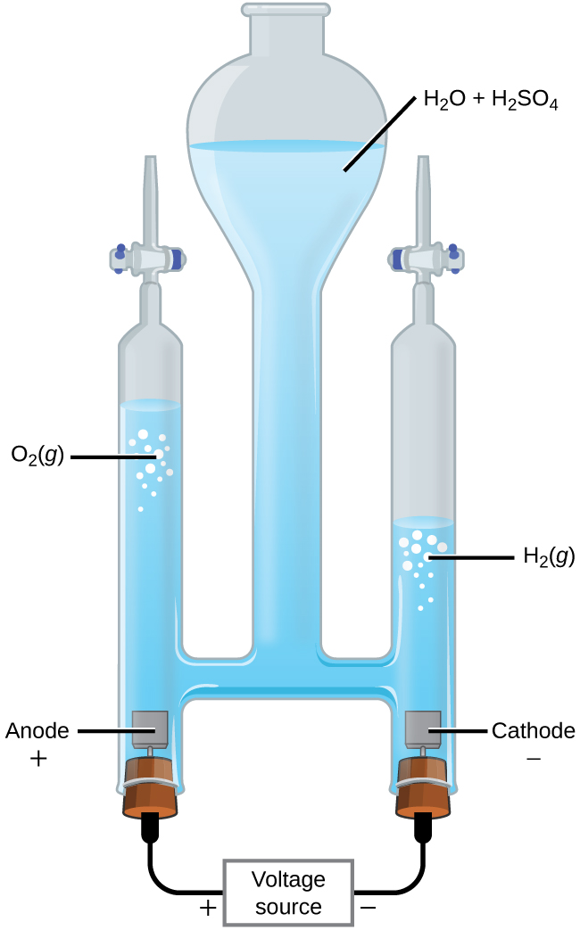
In 1-M acidic solution the reactions and potentials are

[latex]\begin{array}{lrcll} \text{anode:} & 2\;\text{H}_2\text{O}(l) &\longrightarrow& \text{O}_2(\text{g})\;+\;4\;\text{H}^{+}(\text{aq})\;+\;4\text{e}^{-} & E_{\text{anode}}^{\circ} = +1.229\;\text{V} \\[0.5em] \text{cathode:} & 2\text{H}^{+}(\text{aq})\;+\;2\text{e}^{-} &\longrightarrow& \text{H}_2(\text{g}) & E_{\text{cathode}}^{\circ} = 0\;\text{V} \\[0.5em] \hline \\[-0.25em] \text{overall:} & 2\text{H}_2\text{O}(l) &\longrightarrow& 2\text{H}_2(\text{g})\;+\;\text{O}_2(\text{g}) & E_{\text{cell}}^{\circ} = -1.229\;\text{V} \end{array}[/latex]

At least 1.229 V is required to make this reactant-favored process occur in 1-M H+(aq).

Finally, let’s consider what occurs during the electrolysis of 1-M aqueous potassium iodide. Present in the solution are water molecules, potassium ions, and iodide ions. This example differs from the previous examples because more than one species can be oxidized and more than one species can be reduced. Considering the anode first, the possible oxidation reactions are:

[latex]\begin{array}{lrcll} (\text{i}) & 2\text{I}^{-}(aq) &\longrightarrow& \text{I}_2(aq)\;+\;2\text{e}^{-} & E_{\text{anode}}^{\circ} = +0.535\;\text{V} \\[0.5em] (\text{ii}) & 2\text{H}_2\text{O}(l) &\longrightarrow& \text{O}_2(g)\;+\;4\text{H}^{+}(aq)\;+\;4\text{e}^{-} & E_{\text{anode}}^{\circ} = +1.229\;\text{V} \end{array}[/latex]

(Oxidation of K+ to K2+ is not considered because K+ has a noble-gas electron configuration and therefore a very high ionization energy.) Because [latex]E_{\text{cell}}^{\circ}[/latex] = [latex]E_{\text{cathode}}^{\circ}[/latex] − [latex]E_{\text{anode}}^{\circ}[/latex], the more positive the anode half-cell potential is, the more negative the cell potential is. Therefore, iodide should be oxidized at the anode because it has a less positive half-cell potential. However, the pH of 1-M KI solution is 7, so reaction (ii) is not at standard-state conditions. The Nernst equation, can be applied to half-cell reactions as well as overall cell reactions. We can assume a temperature of 25 °C and that O2 would be produced at 1 bar, so for reaction (ii)

[latex]\begin{array}{l} E = {E^ \circ } - \dfrac{{RT}}{{nF}}\ln \left( {\dfrac{1}{{{{{\rm{[}}{{\rm{H}}^{\rm{ + }}}{\rm{]}}}^{\rm{4}}}}}} \right) = 1.229{\rm{ V}} - \dfrac{{8.414 \times 298.15}}{{4 \times 96485}}\;{\rm{V}} \times \ln \left( {\dfrac{1}{{{{(1 \times {{10}^{ - 7}})}^4}}}} \right)\\[0.3em] {\rm{ }} = 1.229\;{\rm{ V}} - 0.414\;{\rm{ V}} = 0.815\;{\rm{ V}} \end{array}[/latex]

Eanode = 0.815 V for reaction (ii) at pH = 7. This is still higher than for reaction (i), so reaction (i) occurs and I2 forms at the anode.

Now consider the possible reactions at the cathode:

[latex]\begin{array}{rrcll} (\text{iii}) & 2\text{H}_2\text{O}(l)\;+\;2\text{e}^{-} &\longrightarrow& \text{H}_2(g)\;+\;2\text{OH}^{-}(aq) & E_{\text{cathode}}^{\circ} = -0.8277\;\text{V} \\[0.5em] (\text{iv}) & \text{K}^{+}(aq)\;+\;\text{e}^{-} &\longrightarrow& \text{K}(s) & E_{\text{cathode}}^{\circ} = -2.925\;\text{V} \end{array}[/latex]

(Reduction of chloride ion is not considered because Cl has a noble-gas electron configuration and it is difficult to add more electrons.) Reduction of water, reaction (iii) with Ecathode = -0.4136 V at pH = 7 (calculated for nonstandard conditions using the Nernst equation), is much more likely to occur than is reduction of K+(aq) to K(s) with Ecathode = -2.925 V. (This conclusion is supported by the fact that potassium metal reacts vigorously with water to generate K+(aq), hydrogen gas, and hydroxide ions, so if K(s) formed it would immediately react with water.)

The overall reaction is then:

2 H2O(l) + 2 I¯(aq) ⟶ H2(g) + I2(aq) + 2 OH¯(aq)     E°cell = -1.229 V

Electroplating

An important use for electrolytic cells is electroplating, which results in a thin coating of one metal on top of a conducting surface. The metals commonly used in electroplating include cadmium, chromium, copper, gold, nickel, silver, and tin. We can get an idea of how this works by investigating how silver-plated tableware is produced (Figure 5).

This figure contains a diagram of an electrochemical cell. One beakers is shown that is just over half full. The beaker contains a clear, colorless solution that is labeled “A g N O subscript 3 ( a q ).” A silver strip is mostly submerged in the liquid on the left. This strip is labeled “Silver (anode).” The top of the strip is labeled with a red plus symbol. An arrow points right from the surface of the metal strip into the solution to the label “A g superscript plus” to the right. A spoon is similarly suspended in the solution and is labeled “Spoon (cathode).” It is labeled with a black negative sign on the tip of the spoon’s handle above the surface of the liquid. An arrow extends from the label “A g superscript plus” to the spoon on the right. A wire extends from the top of the spoon and the strip to a rectangle labeled “Voltage source.” An arrow points upward from silver strip which is labeled “e superscript negative.” Similarly, an arrow points down at the right to the surface of the spoon which is also labeled “e superscript negative.” A plus sign is shown just outside the voltage source to the left and a negative is shown to its right.
Figure 4. The spoon, which is made of an inexpensive metal, is connected to the negative terminal of the voltage source and acts as the cathode. The anode is a silver electrode. Both electrodes are immersed in a silver nitrate solution. When a steady current is passed through the solution, the net result is that silver metal is removed from the anode and deposited on the cathode.

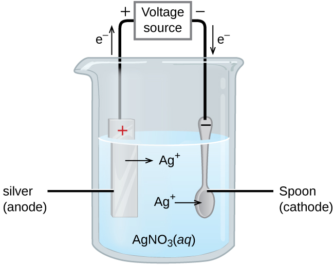
The anode consists of a silver electrode. The cathode is a spoon made from an inexpensive metal. Both electrodes are immersed in a solution of silver nitrate. As the potential is increased, current flows. Silver metal is lost at the anode as it goes into solution:

anode:  Ag(s) ⟶ Ag+(aq) + e

The mass of the cathode increases as silver ions from the solution are deposited onto the spoon:

cathode: Ag+(aq) + e ⟶ Ag(s)

The net result is the transfer of silver metal from the anode to the cathode. The quality of the electroplated object depends on the thickness of the deposited silver and the rate of deposition.

D42.3 Quantitative Aspects of Electrolysis

The quantity of current that is allowed to flow in an electrolytic cell is related to the amount (mol) of electrons, which is related to quantities of reactants and products using reaction stoichiometry. Recall that the SI unit for current (I) is the ampere (1 A = 1 C/s). The total charge (Q, in coulombs) is therefore related to current and the time the current flows. It is also related to the amount of electrons (n):

Q = I × t = (amount e) × F

where F is the Faraday constant.

Example 1

Determining Amount of Electrons from Current and Time
In one process used for electroplating silver, a current of 10.23 A was passed through an electrolytic cell for exactly 1 hour. Calculate how many moles of electrons passed through the cell. What mass of silver was deposited at the cathode from the silver nitrate solution?

Solution
Faraday’s constant can be used to convert the charge (Q) into moles of electrons (n). The charge is the current (I) multiplied by the time:

[latex]\text{amount e}^- = \dfrac{Q}{F} = \dfrac{I\times t}{F} =\dfrac{(10.23\;\text{C/s})\;(1\;\text{h})\;(60\;\text{min/h})\;(60\;\text{s/min})}{96,485\;\text{C/mol e}^{-}} = \dfrac{36,830\;\text{C}}{96,485\;\text{C/mol e}^{-}} = 0.3817\;\text{mol e}^{-}[/latex]

The electroplating solution contains AgNO3, so the reaction at the cathode involves 1 mol electrons for each 1 mol silver:

[latex]\text{cathode:}\;\text{Ag}^{+}(\text{aq})\;+\;\text{e}^{-}\;{\longrightarrow}\;\text{Ag}(\text{s})[/latex]

The atomic mass of silver is 107.9 g/mol, so:

[latex]\text{mass Ag deposited} = 0.3817\;\text{mol e}^{-}\;\times\;\dfrac{1\;\text{mol Ag}}{1\;\text{mol e}^{-}}\;\times\;\dfrac{107.9\;\text{g Ag}}{1\;\text{mol Ag}} = 41.19\;\text{g Ag}[/latex]

Check your answer: From the stoichiometry, 1 mol electrons would produce 1 mol silver. Less than one-half mol electrons was involved and less than one-half mol silver was produced.

Check Your Learning
Aluminum metal can be made by electrolysis from bauxite ore, which contains aluminum ions . Write the half-reaction at the cathode. Determine the mass of aluminum metal produced if a current of 2.50 × 10³ A passed through the solution for 15.0 minutes? Assume the yield is 100%.

Answer:

[latex]\text{Al}^{3+}(\text{aq})\;+\;3\text{e}^{-}\;{\longrightarrow}\;\text{Al}(\text{s})[/latex]; 7.77 mol Al; 210. g Al.

Podia Question

To prepare part of a chromium-plated sculpture, a 0.010-mm thick layer of chromium must be deposited on a part with a total surface area of 3.3 m2 from a solution containing chromium(III) ions. How long would it take to deposit the layer of chromium if the current is 33.46 A? The density of chromium (metal) is 7.19 g/cm3.

Two days before the next whole-class session, this Podia question will become live on Podia, where you can submit your answer.

License

Icon for the Creative Commons Attribution-NonCommercial-ShareAlike 4.0 International License

Chemistry 109 Copyright © by John Moore; Jia Zhou; and Etienne Garand is licensed under a Creative Commons Attribution-NonCommercial-ShareAlike 4.0 International License, except where otherwise noted.