"

Additional Reading Materials

Chapter 4: Covalent Bond and Lewis Structure

Ch4.1 Covalent Bond

In ionic compounds, electrons are transferred between atoms of different elements to form ions. But this is not the only way that compounds can be formed. Atoms can also make chemical bonds by sharing electrons between each other. Such bonds are called covalent bonds. Covalent bonds are formed between two atoms when both have similar tendencies to attract electrons to themselves (i.e., when both atoms have fairly similar ionization energies and electron affinities). For example, two hydrogen atoms bond covalently to form an H2 molecule; each hydrogen atom in the H2 molecule has two electrons stabilizing it, giving each atom the same number of valence electrons as the noble gas He.

Compounds that contain covalent bonds exhibit different physical properties than ionic compounds. Because the attraction between molecules, which are electrically neutral, is weaker than that between electrically charged ions, covalent compounds generally have much lower melting and boiling points than ionic compounds. In fact, many covalent compounds are liquids or gases at room temperature, and, in their solid states, they are typically much softer than ionic solids. Furthermore, whereas ionic compounds are good conductors of electricity when dissolved in water, most covalent compounds are insoluble in water; since they are electrically neutral, they are poor conductors of electricity in any state.

Formation of Covalent Bonds

Nonmetal atoms frequently form covalent bonds with other nonmetal atoms. For example, the hydrogen molecule, H2, contains a covalent bond between its two hydrogen atoms. Figure 1 illustrates why this bond is formed. Starting on the far right, we have two separate hydrogen atoms with a particular potential energy, indicated by the red line. Along the x-axis is the distance between the two atoms. As the two atoms approach each other (moving left along the x-axis), their valence orbitals (1s) begin to overlap. The single electrons on each hydrogen atom then interact with both atomic nuclei, occupying the space around both atoms. The strong attraction of each shared electron to both nuclei stabilizes the system, and the potential energy decreases as the bond distance decreases. If the atoms continue to approach each other, the positive charges in the two nuclei begin to repel each other, and the potential energy increases. The bond length is determined by the distance at which the lowest potential energy is achieved.
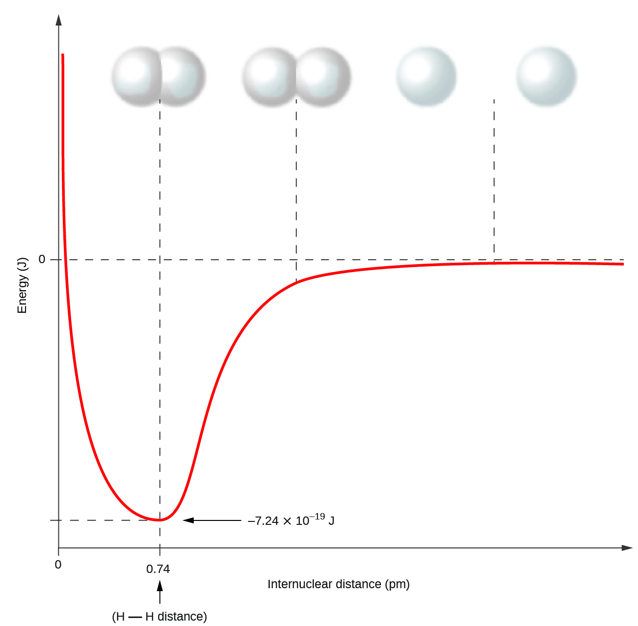
A graph is shown with the x-axis labeled, “Internuclear distance ( p m )” while the y-axis is labeled, “Energy ( J ).” One value, “0,” is labeled midway up the y-axis and two values: “0” at the far left and “0.74” to the left, are labeled on the x-axis. The point “0.74” is labeled, “H bond H distance.” A line is graphed that begins near the top of the y-axis and to the far left on the x-axis and drops steeply to a point labeled, “negative 7.24 times 10 superscript negative 19 J” on the y-axis and 0.74 on the x-axis. This low point on the graph corresponds to a drawing of two spheres that overlap considerably. The line then rises to zero on the y-axis and levels out. The point where it almost reaches zero corresponds to two spheres that overlap slightly. The line at zero on the y-axis corresponds to two spheres that are far from one another.
Figure 1. The potential energy of two separate hydrogen atoms (right) decreases as they approach each other, and the single electrons on each atom are shared to form a covalent bond. The bond length is the internuclear distance at which the lowest potential energy is achieved.

It is essential to remember that energy must be added to break chemical bonds (an endothermic process), whereas forming chemical bonds releases energy (an exothermic process). In the case of H2, the covalent bond is very strong; a large amount of energy, 436 kJ, must be added to break the bonds in one mole of hydrogen molecules and cause the atoms to separate:

[latex]\text{H}_2(g) \longrightarrow 2\text{H}(g) \;\;\;\;\; \Delta H = 436\;\text{kJ}[/latex]

Conversely, the same amount of energy is released when one mole of H2 molecules forms from two moles of H atoms:

[latex]2\text{H}(g) \longrightarrow \text{H}_2(g) \;\;\;\;\; \Delta H = -436 \;\text{kJ}[/latex]

Ch4.2 Molecular Orbital Theory

Molecular orbital (MO) theory describes the distribution of electrons in a molecule in much the same way that the distribution of electrons in an atom is described using atomic orbitals. Using quantum mechanics, the behavior of an electron in a molecule is also described by a wave function, Ψ, analogous to the behavior in an atom. Just like electrons around isolated nucleus, electrons around nucleus in molecules are limited to discrete (quantized) energies. The region of space in which an electron in a molecule is likely to be found is called a molecular orbital. Like an atomic orbital, a single molecular orbital is full when it contains two electrons with opposite spin.

We will first consider the molecular orbitals in molecules composed of two identical atoms (H2 or Cl2, for example). Such molecules are called homonuclear diatomic molecules. In these diatomic molecules, several types of molecular orbitals occur.

The mathematical process of combining atomic orbitals to generate molecular orbitals is called the linear combination of atomic orbitals (LCAO). The wave function describes the wavelike properties of an electron. Molecular orbitals are combinations of atomic orbital wave functions. Combining waves can lead to constructive interference, in which peaks line up with peaks, or destructive interference, in which peaks line up with troughs (Figure 2). In orbitals, the waves are three dimensional, and they can combine in-phase, producing regions with a higher probability of electron density, or out-of-phase, producing nodes or regions of low electron density.

A pair of diagrams are shown and labeled, “a” and “b.” Diagram a shows two identical waves with two crests and two troughs. They are drawn one above the other with a plus sign in between and an equal sign to the right. To the right of the equal sign is a much taller wave with a same number of troughs and crests. Diagram b shows two waves with two crests and two troughs, but they are mirror images of one another rotated over a horizontal axis. They are drawn one above the other with a plus sign in between and an equal sign to the right. To the right of the equal sign is a flat line.
Figure 2. (a) When in-phase waves combine, constructive interference produces a wave with greater amplitude. (b) When out-of-phase waves combine, destructive interference produces a wave with less (or no) amplitude.

There are two types of molecular orbitals that can form from the overlap of two atomic s orbitals on adjacent atoms, illustrated in Figure 3. The in-phase combination produces a σs molecular orbital (read as “sigma-s”) in which most of the electron density is located between the nuclei and are attracted by both nuclei at the same time. The σs MO is more stable (lower energy) than the individual atom orbitals and contribute to the formation of a covalent bond. Therefore we call these bonding orbitals. The out-of-phase combination (which can also be thought of as subtracting the wave functions) produces a σs* molecular orbital (read as “sigma-s-star”) in which the electron density is located well away from the region between the two nuclei, and there is a node between the nuclei. The σs* MO is higher in energy than the individual atom orbitals and thus makes a negative contribution to bonding. These orbitals are called antibonding orbitals, denoted by the asterisk.
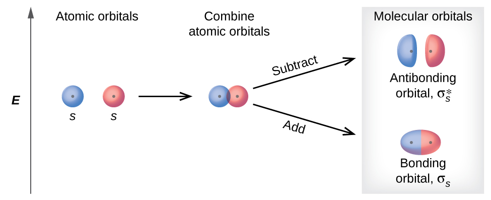
A diagram is shown that depicts a vertical upward-facing arrow that lies to the left of all the other portions of the diagram and is labeled, “E.” To the immediate right of the midpoint of the arrow are two circles each labeled with a positive sign, the letter S, and the phrase, “Atomic orbitals.” These are followed by a right-facing horizontal arrow that points to the same two circles labeled with plus signs, but they are now touching and are labeled, “Combine atomic orbitals.” Two right-facing arrows lead to the last portion of the diagram, one facing upward and one facing downward. The upper arrow is labeled, “Subtract,” and points to two oblong ovals labeled with plus signs, and the phrase, “Antibonding orbitals sigma subscript s superscript asterisk.” The lower arrow is labeled, “Add,” and points to an elongated oval with two plus signs that is labeled, “Bonding orbital sigma subscript s.” The heading over the last section of the diagram are the words, “Molecular orbitals.”
Figure 3. σs and σs* molecular orbitals are formed by the combination of two atomic s orbitals. The dots indicate the locations of nuclei. The red and blue colors only serve to differentiate the two atoms.

You can watch animations visualizing the calculated atomic orbitals combining to form various molecular orbitals at the Orbitron website.

In p atomic orbitals, the wave function gives rise to two lobes with opposite phases, analogous to how a two-dimensional wave has both parts above and below the average. We indicate the phases by shading the orbital lobes differently or by using different colors. When orbital lobes of the same phase overlap, constructive interference increases the electron density. When regions of opposite phase overlap, the destructive interference decreases electron density and creates nodes. When p orbitals overlap end to end, they create σp and σp* molecular orbitals (Figure 4). If two atoms are located along the x-axis in a Cartesian coordinate system, the two px orbitals overlap end to end and form σpx (bonding) and [latex]\sigma^*_{px}[/latex] (antibonding) molecular orbitals. Just as with s-orbital overlap, the asterisk indicates the MO with antibonding characteristic that is higher in energy than the atomic p orbital used to form it.

Two horizontal rows of diagrams are shown. The upper diagram shows two equally-sized peanut-shaped orbitals with a plus sign in between them connected to a merged orbital diagram by a right facing arrow. The merged diagram has a much larger oval at the center and much smaller ovular orbitals on the edge. It is labeled, “sigma subscript p x.” The lower diagram shows two equally-sized peanut-shaped orbitals with a plus sign in between them connected to a split orbital diagram by a right facing arrow. The split diagram has a much larger oval at the outer ends and much smaller ovular orbitals on the inner edges. It is labeled, “sigma subscript p x superscript asterisk”.
Figure 4. Combining wave functions of two p atomic orbitals along the internuclear axis creates two molecular orbitals, σp and σ*p.  Here, the red and blue colors denote different phases of the orbitals.

The side-by-side overlap of two atomic p orbitals gives rise to a π and a π* molecular orbitals, as shown in Figure 5. The π MO contains a nodal plane along the internuclear axis and perpendicular to the lobes of the p orbitals, with electron density on either side of the node.  This nodal plane connects the node that was present in the atomic p orbitals.  An electron in the π MO interacts with both nuclei and has an energy lower than it would in the atomic p orbital, making this a bonding MO. The π* MO has an additional perpendicular nodal plane between the nuclei.  It is higher in energy than the atomic p orbital and has antibonding characteristic.
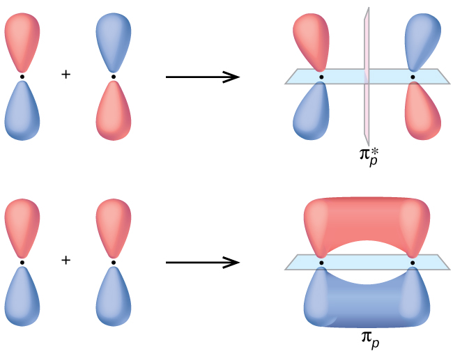
Two horizontal rows of diagrams are shown. The upper and lower diagrams both begin with two vertical peanut-shaped orbitals with a plus sign in between followed by a right-facing arrow. The upper diagram shows the same vertical peanut orbitals bending slightly away from one another and separated by a dotted line. It is labeled, “pi subscript p superscript asterisk.” The lower diagram shows the horizontal overlap of the two orbitals and is labeled, “pi subscript p.”
Figure 5. Side-by-side overlap of two p orbitals results in the formation of π molecular orbitals. Combining the out-of-phase orbitals results in an antibonding molecular orbital with two nodes, one along the internuclear axis and one perpendicular to the axis. Combining the in-phase orbitals results in a bonding molecular orbital. There is a node along the internuclear axis with the two lobes of the orbital located above and below this node.

Of the three atomic p orbitals, two would orient side by side (py and pz), which can combine to create π and π* molecular orbitals. The πpy and [latex]\pi^*_{py}[/latex] MOs are oriented perpendicular to the πpz and [latex]\pi^*_{pz}[/latex] MOs, just as the atomic py and pz orbitals are perpendicular to each other. Except for their orientation, the πpy and πpz MOs are identical and have the same energy; they are degenerate orbitals. The [latex]\pi^*_{py}[/latex] and [latex]\pi^*_{px}[/latex] antibonding orbitals are also degenerate and identical except for their orientations.

Example 1

Molecular Orbitals
Predict what type of molecular orbital (if any) would result from combination of atomic orbitals as shown.  The red and blue colors here denote the different phases in the atomic p orbital.

Three diagrams are shown and labeled “a,” “b,” and “c.” Diagram a shows two horizontal peanut-shaped orbitals laying side-by-side. They are labeled, “3 p subscript x and 3 p subscript x.” Diagram b shows one vertical and one horizontal peanut-shaped orbital which are at right angles to one another. They are labeled, “3 p subscript x and 3 p subscript y.” Diagram c shows two vertical peanut-shaped orbitals laying side-by-side and labeled, “3 p subscript y and 3 p subscript y.”

Solution
(a) is an in-phase combination, resulting in a σ3p molecular orbital.

(b) will not result in a molecular orbital because the constructive and destructive interference would cancel each other out (the in-phase and out-of-phase component of one atomic orbital would overlap with the same lobe on the other atomic orbital). Only orbitals with the correct alignment can combine.

(c) is an out-of-phase combination, resulting in a [latex]\pi^*_{3p}[/latex] orbital.

Check Your Learning
Label the molecular orbital shown as σ or π, bonding or antibonding and indicate where the node occurs.

Two orbitals are shown lying end-to-end. Each has one enlarged and one small side. The small sides are facing one another

Answer:

The orbital is located along the internuclear axis, so it is a σ orbital. There is a node bisecting the internuclear axis, so it is an antibonding orbital.

Two orbitals are shown lying end-to-end. Each has one enlarged and one small side. The small sides are facing one another and are separated by a vertical dotted line.

Walter Kohn: Nobel Laureate

Walter Kohn (Figure 6) is a theoretical physicist who studies the electronic structure of solids. His work combines the principles of quantum mechanics with advanced mathematical techniques. This technique, called density functional theory, makes it possible to compute properties of molecular orbitals, including their shape and energies. Kohn and mathematician John Pople were awarded the Nobel Prize in Chemistry in 1998 for their contributions to our understanding of electronic structure. Kohn also made significant contributions to the physics of semiconductors.

A photograph of Walter Kohn is shown.
Figure 6. Walter Kohn developed methods to describe molecular orbitals. (credit: image courtesy of Walter Kohn)

Kohn’s biography has been remarkable outside the realm of physical chemistry as well. He was born in Austria, and during World War II he was part of the Kindertransport program that rescued 10,000 children from the Nazi regime. His summer jobs included discovering gold deposits in Canada and helping Polaroid explain how its instant film worked.

Computational Chemistry in Drug Design

While the descriptions of bonding described in this chapter involve many theoretical concepts, they also have many practical, real-world applications. For example, drug design is an important field that uses our understanding of chemical bonding to develop pharmaceuticals. This interdisciplinary area of study uses biology (understanding diseases and how they operate) to identify specific targets, such as a binding site that is involved in a disease pathway. By modeling the structures of the binding site and potential drugs, computational chemists can predict which structures can fit together and how effectively they will bind (see Figure 7). Thousands of potential candidates can be narrowed down to a few of the most promising candidates. These candidate molecules are then carefully tested to determine side effects, how effectively they can be transported through the body, and other factors. Dozens of important new pharmaceuticals have been discovered with the aid of computational chemistry, and new research projects are underway.
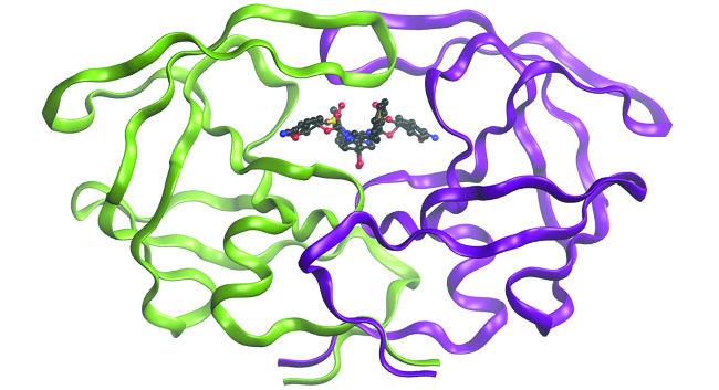
A diagram of a molecule is shown. The image shows a tangle of ribbon-like, intertwined, pink and green curling lines with a complex ball and stick model in the center.
Figure 7. The molecule shown, HIV-1 protease, is an important target for pharmaceutical research. By designing molecules that bind to this protein, scientists are able to drastically inhibit the progress of the disease.

Ch4.3 Molecular Orbital Energy Diagram and Bond Order

The relative energy levels of atomic and molecular orbitals are typically shown in a molecular orbital diagram (Figure 8). For a diatomic molecule, the atomic orbitals of one atom are shown on the left, and those of the other atom are shown on the right. Each horizontal line represents one orbital that can hold two electrons. The molecular orbitals formed by the combination of the atomic orbitals are shown in the center. Dashed lines show which of the atomic orbitals combined to form the molecular orbitals. For homonuclear diatomic molecules, each pair of atomic orbitals that combine would form one lower-energy (bonding) and one higher-energy (antibonding) molecular orbital. Thus we can see that combining the six 2p atomic orbitals results in three bonding orbitals (one σ and two π) and three antibonding orbitals (one σ* and two π*).

We predict the electron occupation in these molecular orbitals by filling them in the same way that we fill atomic orbitals, by the Aufbau principle. Lower-energy orbitals fill first, electrons spread out among degenerate orbitals before pairing up, and each molecular orbital can hold a maximum of two electrons with opposite spins. Figure 8 shows the example of Be2+.
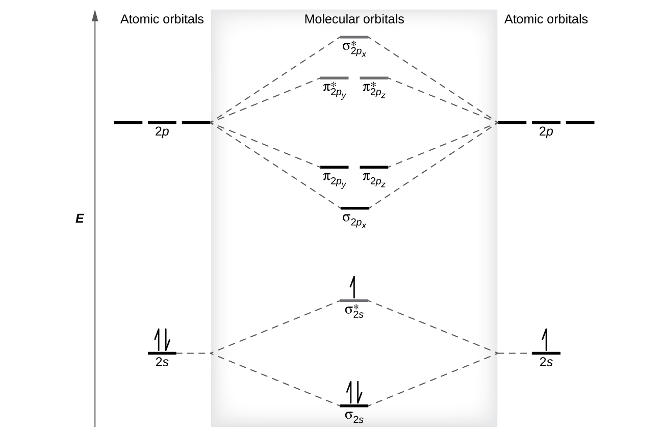
A diagram is shown that has an upward-facing vertical arrow running along the left side labeled, “E.” At the bottom center of the diagram is a horizontal line labeled, “sigma subscript 2 s,” that has two vertical half arrows drawn on it, one facing up and one facing down. This line is connected to the right and left by upward-facing, dotted lines to two more horizontal lines, each labeled, “2 s.” The line on the left has two vertical half arrows drawn on it, one facing up and one facing down while the line of the right has one half arrow facing up drawn on it. These two lines are connected by upward-facing dotted lines to another line in the center of the diagram, but further up from the first. It is labeled, “sigma subscript 2 s superscript asterisk.” This horizontal line has one upward-facing vertical half-arrow drawn on it. Moving farther up the center of the diagram is a long horizontal line labeled, “sigma subscript 2 p subscript x,” which lies below two horizontal lines. These two horizontal lines lie side-by-side, and labeled, “pi subscript 2 p subscript y,” and, “pi subscript 2 p subscript z.” Both the bottom and top lines are connected to the right and left by upward-facing, dotted lines to three more horizontal lines, each labeled, “2 p.” These sets of lines are connected by upward-facing dotted lines to another single line and then pair of double lines in the center of the diagram, but farther up from the lower lines. They are labeled, “sigma subscript 2 p subscript x superscript asterisk,” and, ““pi subscript 2 p subscript y superscript asterisk,” and, “pi subscript 2 p subscript z superscript asterisk,” respectively. The left and right sides of the diagram have headers that read, ”Atomic orbitals,” while the center is header reads “Molecular orbitals”.
Figure 8. This is the molecular orbital diagram for the homonuclear diatomic Be2+, showing the valence shell only. The molecular orbitals are filled in the same manner as atomic orbitals, using the Aufbau principle and Hund’s rule.

Just as we write electron configurations for atoms, we can write the molecular electronic configuration by listing the orbitals with superscripts indicating the number of electrons present. For Be2+, it would be [latex](\sigma_{1s})^2 (\sigma^*_{1s})^2 (\sigma_{2s})^2 (\sigma^*_{2s})^1[/latex]. For clarity, we place parentheses around molecular orbitals with the same energy. For simplicity, it is common to omit the core electrons from molecular orbital diagrams and include only the valence electrons.

The net contribution of the electrons to the bond strength of a molecule is identified by determining the bond order that results from the occupation of the molecular orbitals by electrons. Generally, a single bond has a bond order of 1, a double bond has a bond order of 2, and a triple bond has a bond order of 3.

An electron contributes to a bonding interaction if it occupies a bonding orbital and it contributes to an antibonding interaction if it occupies an antibonding orbital. The bond order is calculated by subtracting the destabilizing (antibonding) electrons from the stabilizing (bonding) electrons. Since a bond consists of two electrons, we divide by two to get the bond order. We can determine bond order with the following equation:

[latex]\text{bond order} = \frac{(\text{number of bonding electrons}) - (\text{number of antibonding electrons})}{2}[/latex]

The order of a covalent bond is a guide to its strength; a bond between two atoms is stronger if the bond order is higher. We next look at some specific examples of MO diagrams and bond orders.

Ch4.4 Bonding in Diatomic Molecules

Diatomic Molecules of the First Period

In H2, the AOs of the two atoms combine to form the the σ1s and [latex]\sigma^*_{1s}[/latex] MOs.(Figure 9) The two electrons occupy the lowest energy σ1s bonding MO. From this picture, we know that H2 would readily form because the energy of a H2 molecule is lower than that of two separate H atoms (the σ1s MO is lower in energy than the two 1s atomic orbitals). The electron configuration of H2 is (σ1s)2. A diagram is shown that has an upward-facing vertical arrow running along the left side labeled “E.” At the bottom center of the diagram is a horizontal line labeled, “sigma subscript 1 s,” that has two vertical half arrows drawn on it, one facing up and one facing down. This line is connected to the right and left by upward-facing, dotted lines to two more horizontal lines, each labeled, “1 s,” and each with one vertical half-arrow facing up drawn on it. These two lines are connected by upward-facing dotted lines to another line in the center of the diagram, but farther up from the first, and labeled, “sigma subscript 1 s superscript asterisk.” The left and right sides of the diagram have headers that read, ”Atomic orbitals,” while the center header reads, “Molecular orbitals.” The bottom left and right are labeled “H” while the center is labeled “H subscript 2.”

Figure 9. The molecular orbital energy diagram predicts that H2 is a stable molecule with lower energy than the separated atoms.

A H2 molecule contains two bonding electrons and no antibonding electrons. so it has:

[latex]\text{bond order in H}_2 = \frac{(2 - 0)}{2} = 1[/latex]

This bond is a single bond.

Figure 10 shows the MO diagram of a He2 molecule. There are four electrons in this system, two occupies the σ1s MO and two occupies the [latex]\sigma^*_{1s}[/latex] MO. The bond order would be:

[latex]\text{bond order in He}_2 = \frac{(2 - 2)}{2} = 0[/latex]

A bond order of zero indicates that no bond is formed between two atoms. In other words, the stabilizing effect of the two electrons in the lower-energy bonding MO is offset by the destabilizing effect of the two electrons in the higher-energy antibonding MO, so there is no driving force for helium atoms to form a diatomic molecule. In fact, helium exists as discrete atoms rather than as diatomic molecules.
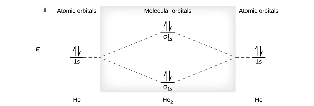
A diagram is shown that has an upward-facing vertical arrow running along the left side labeled, “E.” At the bottom center of the diagram is a horizontal line labeled, “sigma subscript 1 s,” that has two vertical half arrows drawn on it, one facing up and one facing down. This line is connected to the right and left by upward-facing, dotted lines to two more horizontal lines, each labeled, “1 s,” and each with one vertical half-arrow facing up and one facing down drawn on it. These two lines are connected by upward-facing dotted lines to another line in the center of the diagram, but farther up from the first, and labeled, “sigma subscript 1 s superscript asterisk.” This line has one upward-facing and one downward-facing vertical arrow drawn on it. The left and right sides of the diagram have headers that read, “Atomic orbitals,” while the center header reads, “Molecular orbitals.” The bottom left and right are labeled, “H e,” while the center is labeled, “H e subscript 2.”
Figure 10. The molecular orbital energy diagram predicts that He2 will not be a stable molecule, since it has equal numbers of bonding and antibonding electrons.

Diatomic Molecules of the Second Period

Eight possible homonuclear diatomic molecules might be formed by the atoms of the second period of the periodic table: Li2, Be2, B2, C2, N2, O2, F2, and Ne2. The MOs for the valence orbitals of these molecules are shown in Figure 11.
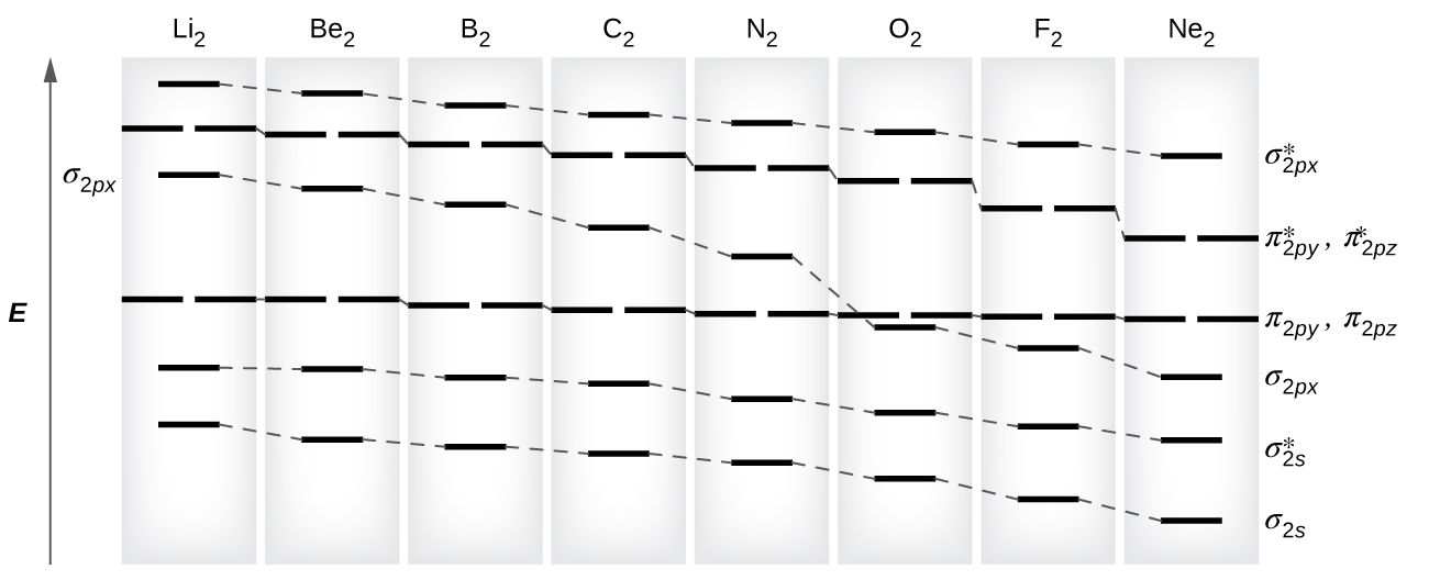
A graph is shown in which the y-axis is labeled, “E,” and appears as a vertical, upward-facing arrow. Across the top, the graph reads, “L i subscript 2,” “B e subscript 2,” “B subscript 2,” “C subscript 2,” “N subscript 2,” “O subscript 2,” “F subscript 2,” and “Ne subscript 2.” Directly below each of these element terms is a single pink line, and all lines are connected to one another by a dashed line, to create an overall line that decreases in height as it moves from left to right across the graph. This line is labeled, “sigma subscript 2 p x superscript asterisk”. Directly below each of these lines is a set of two pink lines, and all lines are connected to one another by a dashed line, to create an overall line that decreases in height as it moves from left to right across the graph. It is consistently lower than the first line. This line is labeled, “pi subscript 2 p y superscript asterisk,” and, “pi subscript 2 p z superscript asterisk.” Directly below each of these double lines is a single pink line, and all lines are connected to one another by a dashed line, to create an overall line that decreases in height as it moves from left to right across the graph. It has a distinctive drop at the label, “O subscript 2.” This line is labeled, “sigma subscript 2 p x.” Directly below each of these lines is a set of two pink lines, and all lines are connected to one another by a dashed line to create an overall line that decreases very slightly in height as it moves from left to right across the graph. It is consistently lower than the third line until it reaches the point labeled, “O subscript 2.” This line is labeled, “pi subscript 2 p y,” and, “pi subscript 2 p z.” Directly below each of these lines is a single blue line, and all lines are connected to one another by a dashed line to create an overall line that decreases in height as it moves from left to right across the graph. This line is labeled, “sigma subscript 2 s superscript asterisk.” Finally, directly below each of these lines is a single blue line, and all lines are connected to one another by a dashed line to create an overall line that decreases in height as it moves from left to right across the graph. This line is labeled. “sigma subscript 2 s.”
Figure 11. The MO diagrams for each homonuclear diatomic molecule in the second period. The orbital energies decrease across the period as the effective nuclear charge increases and atomic radius decreases. Between N2 and O2, the energetic ordering of the orbitals changes.

In molecular orbital theory, σ orbitals are usually more stable than π orbitals formed from degenerate atomic orbitals. However, this is not always the case. Looking at Ne2, we see that the energetic ordering of the MOs is consistent with the generic ordering. However, for atoms with three or fewer electrons in the 2p orbitals (Li through N) we observe a different pattern, in which the σ2p orbital is higher in energy than the π2p.

You can practice labeling and filling molecular orbitals with this interactive tutorial from the University of Sydney.

This switch in orbital ordering occurs because of a phenomenon called s-p mixing. s-p mixing does not create new orbitals; it merely influences the energies of the existing molecular orbitals. The σ2s wavefunction mathematically combines with the σ2p wavefunction, resulting in the σ2s MO becoming more stable and the σ2p MO becoming less stable (Figure 12). Similarly, the antibonding orbitals also undergo s-p mixing, with the σs* becoming more stable and the σp* becoming less stable.
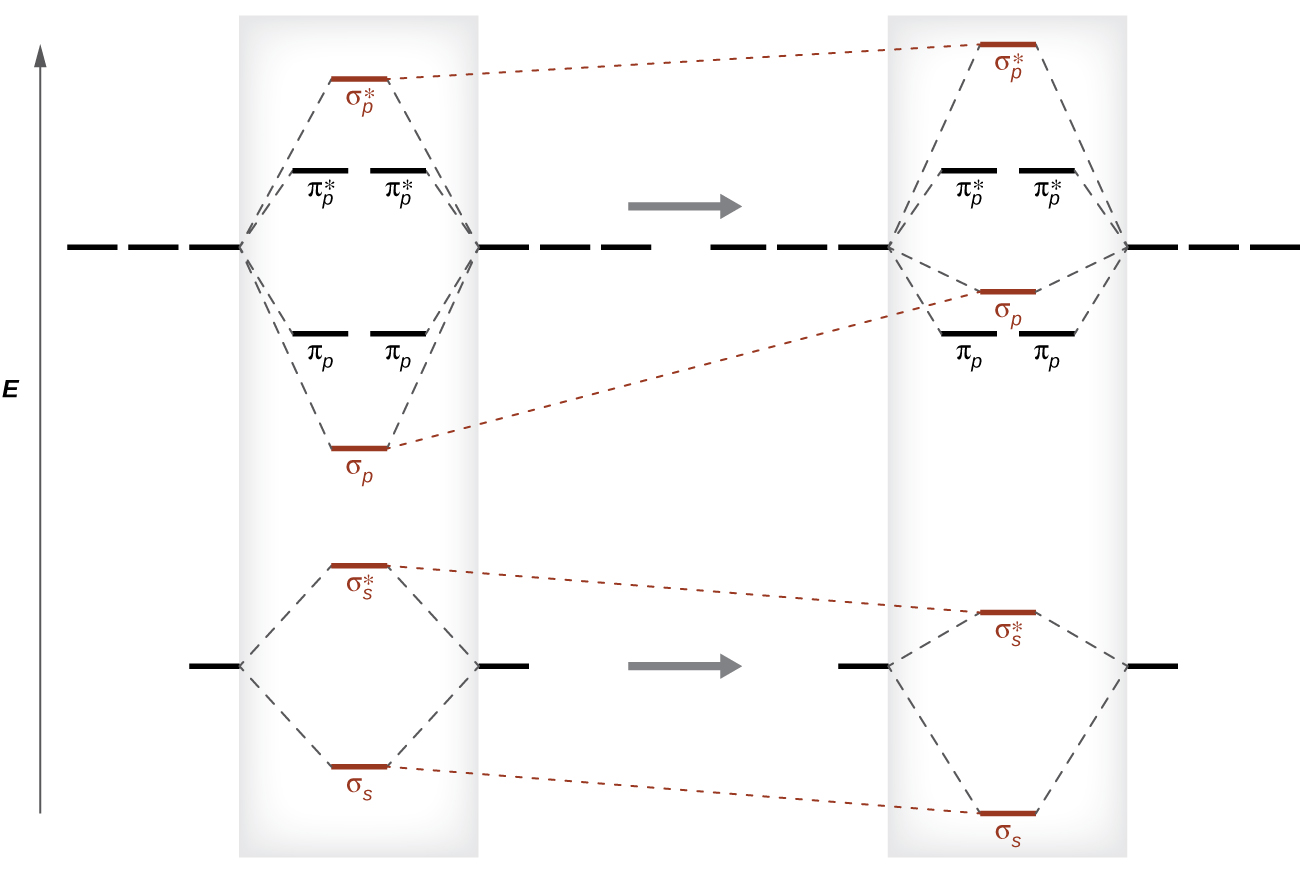
A diagram is shown. At the bottom left of the diagram is a horizontal line that is connected to the right and left by upward-facing, dotted lines to two more horizontal lines. Those two lines are connected by upward-facing dotted lines to another line in the center of the diagram but farther up from the first. Each of the bottom two central lines has a vertical downward-facing arrow. Above this structure is a horizontal line that is connected to the right and left by upward-facing, dotted lines to two sets of three horizontal lines and those two lines are connected by upward-facing dotted lines to another line in the center of the diagram, but further up from the first. In between the horizontal lines of this structure are two pairs of horizontal lines that are above the first line but below the second and connected by dotted lines to the side horizontal lines. The bottom and top central lines each have an upward-facing vertical arrow. These two structures are redrawn on the right side of the diagram, but this time, the central lines of the bottom structure are moved downward in relation to the side lines. The upper portion of the structure has its central lines shifted upward in relation to the side lines. This structure also shows the bottom line appearing above the set of two lines.
Figure 12. Without mixing, the MO pattern occurs as expected, with the σp orbital lower in energy than the πp orbitals. When s-p mixing occurs, the orbitals shift as shown, with the σp orbital higher in energy than the πp orbitals.

s-p mixing occurs when the s and p AOs have similar energies. When a 2p AO contains a pair of electrons, the pairing raises the energy of the orbital. Thus the 2p orbitals for O, F, and Ne are higher in energy than the 2p orbitals for Li, Be, B, C, and N. Hence, O2, F2, and N2 have negligible s-p mixing (not sufficient to change the energy ordering), and the other second period homonuclear diatomic molecules have more s-p mixing that leads to the σ2p raised above π2p.

Using the MO diagrams shown in Figure 11, we can fill in the electrons and determine the molecular electron configuration and bond order for each of the diatomic molecules. As shown in Table 1, Be2 and Ne2 molecules would have a bond order of 0, and these molecules do not exist.

Molecule Electron Configuration Bond Order
Li2 [latex](\sigma_{2s})^2[/latex] 1
Be2 (unstable) [latex](\sigma_{2s})^2 (\sigma^*_{2s})^2[/latex] 0
B2 [latex](\sigma_{2s})^2 (\sigma^*_{2s})^2 (\pi_{2py}, \pi_{2pz})^2[/latex] 1
C2 [latex](\sigma_{2s})^2 (\sigma^*_{2s})^2 (\pi_{2py}, \pi_{2pz})^4[/latex] 2
N2 [latex](\sigma_{2s})^2 (\sigma^*_{2s})^2 (\pi_{2py}, \pi_{2pz})^4 (\sigma_{2px})^2[/latex] 3
O2 [latex](\sigma_{2s})^2 (\sigma^*_{2s})^2 (\sigma_{2px})^2 (\pi_{2py}, \pi_{2pz})^4 (\pi^*_{2py}, \pi^*_{2pz})^2[/latex] 2
F2 [latex](\sigma_{2s})^2 (\sigma^*_{2s})^2 (\sigma_{2px})^2 (\pi_{2py}, \pi_{2pz})^4 (\pi^*_{2py}, \pi^*_{2pz})^4[/latex] 1
Ne2 (unstable) [latex](\sigma_{2s})^2 (\sigma^*_{2s})^2 (\sigma_{2px})^2 (\pi_{2py}, \pi_{2pz})^4 (\pi^*_{2py}, \pi^*_{2pz})^4 (\sigma^*_{2px})^2[/latex] 0
Table 1. Electron Configuration and Bond Order for Molecular Orbitals in Homonuclear Diatomic Molecules of Period Two Elements

Li2 is analogous to H2, but the AOs involved are the valence 2s orbitals. Each of the two lithium atoms has one valence electron. Hence, we have two valence electrons available for the σ2s bonding MO, and we would predict the Li2 molecule to be stable with a bond order of 1. The molecule is, in fact, present in appreciable concentration in lithium vapor at temperatures near the boiling point of the element. All of the other molecules in Table 1 with a bond order greater than zero are also known.

The O2 molecule has enough electrons to half fill the [latex]\pi^*_{2py}[/latex] and [latex]\pi^*_{2pz}[/latex] MOs. We expect the two electrons that occupy these two degenerate orbitals to be unpaired, and this molecular electronic configuration for O2 is in accord with the fact that the oxygen molecule has two unpaired electrons (see Example 2 below). The unpaired electrons of the oxygen molecule provide a strong piece of experimental evidence for the validity of molecular orbital theory.

Band Theory

When two identical atomic orbitals on different atoms combine, two molecular orbitals result. The bonding molecular orbital is lower in energy than the original atomic orbitals. The antibonding molecular orbital is higher in energy than the original atomic orbitals.

In a solid, similar things happen, but on a much larger scale. Remember that even in a small sample there are a huge number of atoms (typically > 1023 atoms), and therefore a huge number of atomic orbitals that may be combined into molecular orbitals. When N valence atomic orbitals, all of the same energy and each containing one electron, are combined, N/2 (filled) bonding molecular orbitals and N/2 (empty) antibonding molecular orbitals will result. Each bonding MO will show an energy lowering as the atomic orbitals are mostly in-phase, but each of the bonding MOs will be a little different and have slightly different energies. The antibonding MOs will show increase in energy as the atomic orbitals are mostly out-of-phase, but each of the antibonding MOs will also be a little different and have slightly different energies. The allowed energy levels for all the bonding MOs are so close together that they form a band, called the valence band. Likewise, all the antibonding MOs are very close together and form a band, called the conduction band. Figure 13 shows the bands for three important classes of materials: insulators, semiconductors, and conductors.
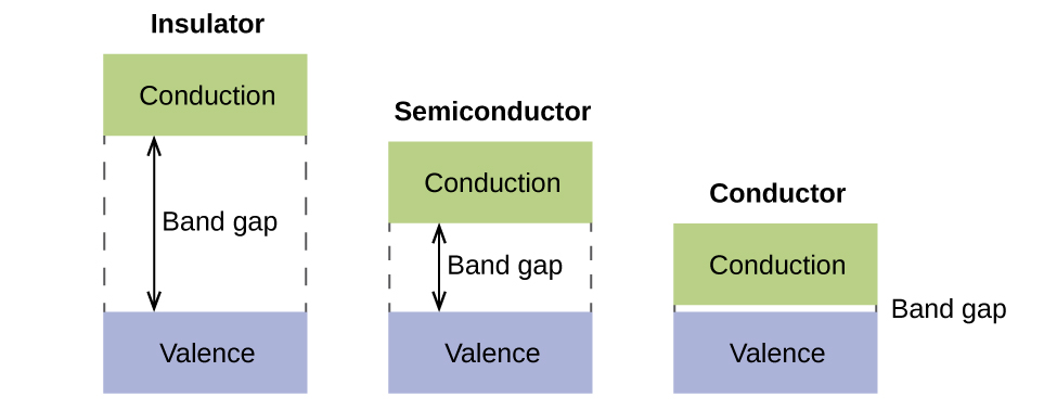
This figure shows three diagrams. The first is labeled, “Insulator,” and it consists of two boxes. The “conduction” box is above and the “valence” box is below. A large gap marked by 4 dashed lines contains a double-headed arrow. One head pointing towards the “conduction box” and the other towards the “valence” box. The arrow is labeled, “Band gap.” The second diagram is similar to the first, but the band gap is about half as large. This diagram is labeled, “Semiconductor.” The third diagram is similar to the other two, but the band gap is about a fifth that of the “Semiconductor” diagram. This diagram is labeled, “Conductor.”
Figure 13. Molecular orbitals in solids are so closely spaced that they are described as bands. The valence band is lower in energy and the conduction band is higher in energy. The type of solid is determined by the size of the “band gap” between the valence and conduction bands. Only a very small amount of energy is required to move electrons from the valance band to the conduction band in a conductor, and so they conduct electricity well. In an insulator, the band gap is large, so that very few electrons move, and they are poor conductors of electricity. Semiconductors are in between: they conduct electricity better than insulators, but not as well as conductors.

In order to conduct electricity, electrons must move from the filled valence band to the empty conduction band where they can move throughout the solid. The size of the band gap, or the energy difference between the top of the valence band and the bottom of the conduction band, determines how easy it is to move electrons between the bands. Only a small amount of energy is required in a conductor because the band gap is very small. This small energy difference is “easy” to overcome, so they are good conductors of electricity. In an insulator, the band gap is so large that very few electrons move into the conduction band; as a result, insulators are poor conductors of electricity. Semiconductors conduct electricity when “moderate” amounts of energy are provided to move electrons out of the valence band and into the conduction band.

Semiconductors, such as silicon, are used in devices such as computers, smartphones, and solar cells. Solar cells produce electricity when sunlight provides the energy to move electrons out of the valence band. The electricity that is generated may then be used to power a light or tool, or it can be stored for later use by charging a battery. As of December 2014, up to 46% of the energy in sunlight could be converted into electricity using solar cells.

Example 2

Molecular Orbital Diagrams, Bond Order, and Number of Unpaired Electrons
Draw the molecular orbital diagram for the oxygen molecule, O2. From this diagram, calculate the bond order for O2. How does this diagram account for the paramagnetism of O2?

Solution

We draw a molecular orbital energy diagram similar to that shown in Figure 11. Each oxygen atom contributes six electrons, so the diagram appears as shown in Figure 14.
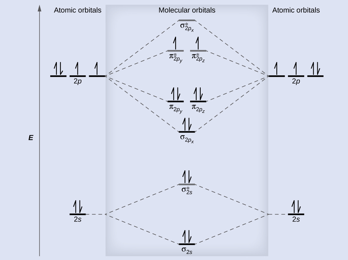
A diagram is shown that has an upward-facing vertical arrow running along the left side labeled, “E.” At the bottom center of the diagram is a horizontal line labeled, “sigma subscript 2 s,” that has two vertical half arrows drawn on it, one facing up and one facing down. This line is connected to the right and left by upward-facing, dotted lines to two more horizontal lines, each labeled, “2 s,” and with two vertical half arrows drawn on them, one facing up and one facing down. These two lines are connected by upward-facing dotted lines to another line in the center of the diagram, but farther up from the first and labeled, “sigma subscript 2 s superscript asterisk.” This horizontal line has two vertical half-arrow drawn on it, one facing up and one facing down. Moving further up the center of the diagram is a horizontal line labeled, “sigma subscript 2 p subscript x,” which lies below two horizontal lines, lying side-by-side, and labeled “pi subscript 2 p subscript y,” and “pi subscript 2 p subscript z.” Both the bottom and top lines are connected to the right and left by upward-facing, dotted lines to three more horizontal lines, each labeled, “2 p,” on either side. These sets of lines each hold three upward-facing and one downward-facing half-arrow. They are connected by upward-facing dotted lines to another single line and then pair of double lines in the center of the diagram, but farther up from the lower lines. They are labeled, “sigma subscript 2 p subscript x superscript asterisk,” “pi subscript 2 p subscript y superscript asterisk,” and “pi subscript 2 p subscript z superscript asterisk,” respectively. The lower of these two central, horizontal lines each contain one upward-facing half-arrow. The left and right sides of the diagram have headers that read, ”Atomic orbitals,” while the center header reads, “Molecular orbitals.”
Figure 14. The molecular orbital energy diagram for O2 predicts two unpaired electrons.

We calculate the bond order as

[latex]\text{O}_2 = \frac{8 - 4}{2} = 2[/latex]

Oxygen has a double bond, and its paramagnetism is explained by the presence of two unpaired electrons in the π2py* and π2pz* molecular orbitals.

Check Your Learning

The main component of air is N2. From the molecular orbital diagram of N2, predict its bond order and whether it is diamagnetic or paramagnetic.

Answer:

N2 has a bond order of 3 and is diamagnetic.

Example 3

Ion Predictions with MO Diagrams
Give the molecular orbital configuration for the valence electrons in C22−. Will this ion be stable?

Solution

Looking at the appropriate MO diagram, we see that the valence electron configuration for C2 is [latex](\sigma_{2s})^2 (\sigma^*_{2s})^2 (\pi_{2py}, \pi_{2pz})^4[/latex]. Adding two more electrons to generate the C22− anion will give a valence electron configuration of [latex](\sigma_{2s})^2 (\sigma^*_{2s})^2 (\pi_{2py}, \pi_{2pz})^4 (\sigma_{2px})^2[/latex]. Since this has six more bonding electrons than antibonding, the bond order will be 3, and the ion should be stable.

Check Your Learning

How many unpaired electrons would be present on a Be22− ion? Would it be paramagnetic or diamagnetic?

Answer:

two, paramagnetic

Creating molecular orbital diagrams for molecules with more than two atoms relies on the same basic ideas as the diatomic examples presented here. See three-dimensional drawings of the molecular orbitals for C6H6.

Ch4.5 Lewis Symbols and Lewis Structures

We use Lewis symbols to describe valence electron configurations of atoms and monatomic ions. A Lewis symbol consists of an elemental symbol surrounded by one dot for each of its valence electrons:

A Lewis structure of calcium is shown. A lone pair of electrons are shown to the right of the symbol.

Figure 15 shows the Lewis symbols for the elements of the third period of the periodic table.

A table is shown that has three columns and nine rows. The header row reads “Atoms,” “Electronic Configuration,” and “Lewis Symbol.” The first column contains the words “sodium,” “magnesium,” “aluminum,” “silicon,” “phosphorus,” “sulfur,” “chlorine,” and “argon.” The second column contains the symbols and numbers “[ N e ] 3 s superscript 2,” “[ N e ] 3 s superscript 2, 3 p superscript 1,” “[ N e ] 3 s superscript 2, 3 p superscript 2,” “[ N e ] 3 s superscript 2, 3 p superscript 3,” “[ N e ] 3 s superscript 2, 3 p superscript 4,” “[ N e ] 3 s superscript 2, 3 p superscript 5,” and “[ N e ] 3 s superscript 2, 3 p superscript 6.” The third column contains Lewis structures for N a with one dot, M g with two dots, A l with three dots, Si with four dots, P with five dots, S with six dots, C l with seven dots, and A r with eight dots.
Figure 15. Lewis symbols illustrating the number of valence electrons for each element in the third period of the periodic table.

Lewis symbols can also be used to illustrate the formation of cations from atoms, as shown here for sodium and calcium:

Two diagrams are shown. The left diagram shows a Lewis dot structure of sodium with one dot, then a right-facing arrow leading to a sodium symbol with a superscripted plus sign, a plus sign, and the letter “e” with a superscripted negative sign. The terms below this diagram read “Sodium atom” and “Sodium cation.” The right diagram shows a Lewis dot structure of calcium with two dots, then a right-facing arrow leading to a calcium symbol with a superscripted two and a plus sign, a plus sign, and the value “2e” with a superscripted negative sign. The terms below this diagram read “Calcium atom” and “Calcium cation.”

Likewise, they can be used to show the formation of anions from atoms, as shown here for chlorine and sulfur:

Two diagrams are shown. The left diagram shows a Lewis dot structure of chlorine with seven dots and the letter “e” with a superscripted negative sign, then a right-facing arrow leading to a chlorine symbol with eight dots and a superscripted negative sign. The terms below this diagram read, “Chlorine atom,” and, “Chlorine anion.” The right diagram shows a Lewis dot structure of sulfur with six dots and the symbol “2e” with a superscripted negative sign, then a right-facing arrow leading to a sulfur symbol with eight dots and a superscripted two and negative sign. The terms below this diagram read, “Sulfur atom,” and, “Sulfur anion.”

Figure 16 demonstrates the use of Lewis symbols to show the transfer of electrons during the formation of ionic compounds.
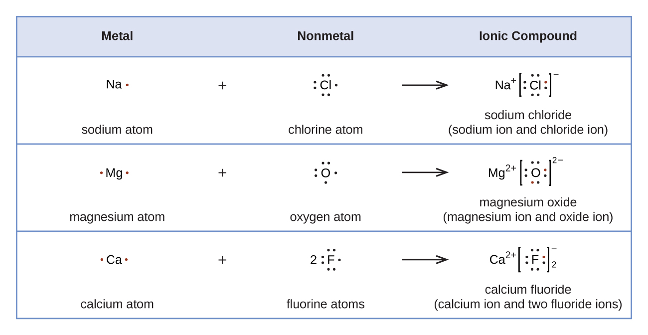
A table is shown with four rows. The header row reads “Metal,” “Nonmetal,” and “Ionic Compound.” The second row shows the Lewis structures of a reaction. A sodium symbol with one dot, a plus sign, and a chlorine symbol with seven dots lie to the left of a right-facing arrow. To the right of the arrow a sodium symbol with a superscripted plus sign is drawn next to a chlorine symbol with eight dots surrounded by brackets with a superscripted negative sign. One of the dots on the C l atom is red. The terms “sodium atom,” “chlorine atom,” and “sodium chloride ( sodium ion and chloride ion )” are written under the reaction. The third row shows the Lewis structures of a reaction. A magnesium symbol with two red dots, a plus sign, and an oxygen symbol with six dots lie to the left of a right-facing arrow. To the right of the arrow a magnesium symbol with a superscripted two and a plus sign is drawn next to an oxygen symbol with eight dots, two of which are red, surrounded by brackets with a superscripted two a and a negative sign. The terms “magnesium atom,” “oxygen atom,” and “magnesium oxide ( magnesium ion and oxide ion )” are written under the reaction. The fourth row shows the Lewis structures of a reaction. A calcium symbol with two red dots, a plus sign, and a fluorine symbol with a coefficient of two and seven dots lie to the left of a right-facing arrow. To the right of the arrow a calcium symbol with a superscripted two and a plus sign is drawn next to a fluorine symbol with eight dots, one of which is red, surrounded by brackets with a superscripted negative sign and a subscripted two. The terms “calcium atom,” “fluorine atoms,” and “calcium fluoride ( calcium ion and two fluoride ions )” are written under the reaction.
Figure 16. Cations are formed when atoms lose electrons, represented by fewer Lewis dots, whereas anions are formed by atoms gaining electrons. The total number of electrons does not change.

We also use Lewis symbols to indicate the formation of covalent bonds, which are shown in Lewis structures, drawings that describe the bonding in molecules and polyatomic ions. For example, when two chlorine atoms form a chlorine molecule, they share one pair of electrons:

A Lewis dot diagram shows a reaction. Two chlorine symbols, each surrounded by seven dots are separated by a plus sign. The dots on the first atom are all black and the dots on the second atom are all read. The phrase, “Chlorine atoms” is written below. A right-facing arrow points to two chlorine symbols, each with six dots surrounding their outer edges and a shared pair of dots in between. One of the shared dots is black and one is red. The phrase, “Chlorine molecule” is written below.

The Lewis structure indicates that each Cl atom has three pairs of electrons that are not used in bonding (called lone pairs) and one shared pair of electrons (written between the atoms). A line is often used to indicate a shared pair of electrons:

Two Lewis structures are shown. The left-hand structure shows two H atoms connected by a single bond. The right-hand structure shows two C l atoms connected by a single bond and each surrounded by six dots.

A single shared pair of electrons is called a single bond. Each Cl atom interacts with eight valence electrons: the six in the lone pairs and the two in the single bond.

The Octet Rule

The other halogen molecules (F2, Br2, I2, and At2) form bonds like those in the chlorine molecule: one single bond between atoms and three lone pairs of electrons per atom. This allows each halogen atom to have a noble gas electron configuration. The tendency of main group atoms to form enough bonds to obtain eight valence electrons is known as the octet rule.

The number of bonds that an atom can form can often be predicted from the number of electrons needed to reach an octet (eight valence electrons); this is especially true of the nonmetals of the second period of the periodic table (C, N, O, and F). For example, each atom of a group 14 element has four electrons in its outermost shell and therefore requires four more electrons to reach an octet. These four electrons can be gained by forming four covalent bonds, as illustrated here for carbon in CCl4 (carbon tetrachloride) and silicon in SiH4 (silane).

Two sets of Lewis dot structures are shown. The left structures depict five C l symbols in a cross shape with eight dots around each, the word “or” and the same five C l symbols, connected by four single bonds in a cross shape. The name “Carbon tetrachloride” is written below the structure. The right hand structures show a S i symbol, surrounded by eight dots and four H symbols in a cross shape. The word “or” separates this from an S i symbol with four single bonds connecting the four H symbols in a cross shape. The name “Silane” is written below these diagrams.

Because hydrogen only needs two electrons to fill its valence shell, it is an exception to the octet rule. The transition elements also do not follow the octet rule.

Group 15 elements such as nitrogen have five valence electrons in the atomic Lewis symbol: one lone pair and three unpaired electrons. To obtain an octet, these atoms form three covalent bonds, as in NH3 (ammonia). Oxygen and other atoms in group 16 obtain an octet by forming two covalent bonds:
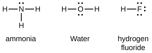
Three Lewis structures labeled, “Ammonia,” “Water,” and “Hydrogen fluoride” are shown. The left structure shows a nitrogen atom with a lone pair of electrons and single bonded to three hydrogen atoms. The middle structure shows an oxygen atom with two lone pairs of electrons and two singly-bonded hydrogen atoms. The right structure shows a hydrogen atom single bonded to a fluorine atom that has three lone pairs of electrons.

Double and Triple Bonds

A pair of atoms may need to share more than one pair of electrons in order to achieve the requisite octet. A double bond forms when two pairs of electrons are shared between a pair of atoms, as between the carbon and oxygen atoms in CH2O (formaldehyde) and between the two carbon atoms in C2H4 (ethylene):

Two pairs of Lewis structures are shown. The left pair of structures shows a carbon atom forming single bonds to two hydrogen atoms. There are four electrons between the C atom and an O atom. The O atom also has two pairs of dots. The word “or” separates this structure from the same diagram, except this time there is a double bond between the C atom and O atom. The name, “Formaldehyde” is written below these structures. A right-facing arrow leads to two more structures. The left shows two C atoms with four dots in between them and each forming single bonds to two H atoms. The word “or” lies to the left of the second structure, which is the same except that the C atoms form double bonds with one another. The name, “Ethylene” is written below these structures.

A triple bond forms when three electron pairs are shared by a pair of atoms, as in carbon monoxide (CO) and the cyanide ion (CN):

Two pairs of Lewis structures are shown and connected by a right-facing arrow. The left pair of structures show a C atom and an O atom with six dots in between them and a lone pair on each. The word “or” and the same structure with a triple bond in between the C atom and O atom also are shown. The name “Carbon monoxide” is written below this structure. The right pair of structures show a C atom and an N atom with six dots in between them and a lone pair on each. The word “or” and the same structure with a triple bond in between the C atom and N atom also are shown. The name “Cyanide ion” is written below this structure.

Ch4.6 Writing Lewis Structures with the Octet Rule

For very simple molecules and molecular ions, we can write the Lewis structures by merely pairing up the unpaired electrons on the constituent atoms. See these examples:
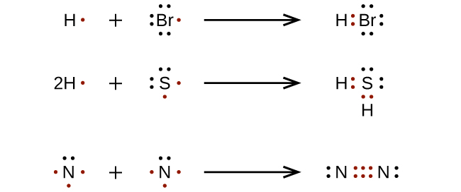
Three reactions are shown with Lewis dot diagrams. The first shows a hydrogen with one red dot, a plus sign and a bromine with seven dots, one of which is red, connected by a right-facing arrow to a hydrogen and bromine with a pair of red dots in between them. There are also three lone pairs on the bromine. The second reaction shows a hydrogen with a coefficient of two and one red dot, a plus sign, and a sulfur atom with six dots, two of which are red, connected by a right facing arrow to two hydrogen atoms and one sulfur atom. There are two red dots in between the two hydrogen atoms and the sulfur atom. Both pairs of these dots are red. The sulfur atom also has two lone pairs of dots. The third reaction shows two nitrogen atoms each with five dots, three of which are red, separated by a plus sign, and connected by a right-facing arrow to two nitrogen atoms with six red electron dots in between one another. Each nitrogen atom also has one lone pair of electrons.

For more complicated molecules and molecular ions, it is helpful to follow a step-by-step procedure such as the one outlined here:

  1. Determine the total number of valence (outer shell) electrons. For cations, subtract one electron for each positive charge. For anions, add one electron for each negative charge.
  2. Draw a skeleton structure of the molecule or ion, arranging the atoms around a central atom. Connect each atom to the central atom with a single bond (one electron pair).
  3. Distribute the remaining electrons as lone pairs on the terminal atoms (except hydrogen), completing an octet around each atom.
  4. Place all remaining electrons on the central atom.
  5. Rearrange the electrons of the outer atoms to make multiple bonds with the central atom in order to obtain octets wherever possible.

Let us determine the Lewis structures of SiH4, CHO2−, NO+, and OF2 as examples in following this procedure:

  1. Determine the total number of valence (outer shell) electrons in the molecule or ion.
    • For a molecule, such as SiH4, we add the number of valence electrons on each atom in the molecule:
      Si: 4 valence electrons/atom x 1 atom = 4
      + H: 1 valence electron/atom x 4 atoms = 4
      total valence electrons = 8
    • For a negative ion, such as CHO2, we add the number of valence electrons on the atoms to the number of negative charges on the ion (one electron is gained for each single negative charge):
      C: 4 valence electrons/atom x 1 atom = 4
      + H: 1 valence electron/atom x 1 atom = 1
      + O: 6 valence electrons/atom x 2 atoms = 12
      + 1 additional electron = 1
      total valence electrons = 18
    • For a positive ion, such as NO+, we add the number of valence electrons on the atoms in the ion and then subtract the number of positive charges on the ion (one electron is lost for each single positive charge) from the total number of valence electrons:
      N: 5 valence electrons/atom x 1 atom = 5
      + O: 6 valence electrons/atom x 1 atom = 6
      – 1 fewer electron = -1
      total valence electrons = 10
    • Since OF2 is a neutral molecule, we simply add the number of valence electrons:
      O: 6 valence electrons/atom x 1 atom = 6
      + F: 7 valence electrons/atom x 2 atoms = 14
      total valence electrons = 20
  2. Draw a skeleton structure of the molecule or ion, arranging the atoms around a central atom and connecting each atom to the central atom with a single bond (one electron pair). (Note that we denote ions with brackets around the structure, indicating the charge outside the brackets:)Four Lewis diagrams are shown. The first shows one silicon single boned to four hydrogen atoms. The second shows a carbon which forms a single bond with an oxygen and a hydrogen and a double bond with a second oxygen. This structure is surrounded by brackets and has a superscripted negative sign near the upper right corner. The third structure shows a nitrogen single bonded to an oxygen and surrounded by brackets with a superscripted plus sign in the upper right corner. The last structure shows two fluorine atoms single bonded to a central oxygen.
    • When several arrangements of atoms are possible, as for CHO2, we must use experimental evidence to choose the correct one. In general, the less electronegative elements are more likely to be central atoms. In CHO2, the less electronegative carbon atom occupies the central position with the oxygen and hydrogen atoms surrounding it. Other examples include P in POCl3, S in SO2, and Cl in ClO4. An exception is that hydrogen is almost never a central atom. As the most electronegative element, fluorine also cannot be a central atom.
  3. Distribute the remaining electrons as lone pairs on the terminal atoms (except hydrogen) to complete their valence shells with an octet of electrons.Four Lewis structures are shown. The first shows one silicon single boned to four hydrogen atoms. The second shows a carbon single bonded to two oxygen atoms that each have three lone pairs and single bonded to a hydrogen. This structure is surrounded by brackets and has a superscripted negative sign near the upper right corner. The third structure shows a nitrogen single bonded to an oxygen, each with three lone pairs of electrons. This structure is surrounded by brackets with a superscripted plus sign in the upper right corner. The last structure shows two fluorine atoms, each with three lone pairs of electrons, single bonded to a central oxygen.
    • There are no remaining electrons on SiH4, so it is unchanged.
  4. Place all remaining electrons on the central atom.
    • For SiH4, CHO2, and NO+, there are no remaining electrons; we already placed all of the electrons determined in Step 1.
    • For OF2, we had 16 electrons remaining in Step 3, and we placed 12, leaving 4 to be placed on the central atom:A Lewis structure shows two fluorine atoms, each with three lone pairs of electrons, single bonded to a central oxygen which has two lone pairs of electrons.
  5. Rearrange the electrons of the outer atoms to make multiple bonds with the central atom in order to obtain octets wherever possible.
    • SiH4: Si already has an octet, so nothing needs to be done.
    • CHO2: We have distributed the valence electrons as lone pairs on the oxygen atoms, but the carbon atom lacks an octet:
      Two Lewis diagrams are shown with the word “gives” in between them. The left diagram, surrounded by brackets and with a superscripted negative sign, shows a carbon atom single bonded to two oxygen atoms, each with three lone pairs of electrons. The carbon atom also forms a single bond with a hydrogen atom. A curved arrow points from a lone pair on one of the oxygen atoms to the carbon atom. The right diagram, surrounded by brackets and with a superscripted negative sign, shows a carbon atom single bonded to an oxygen atom with three lone pairs of electrons, double bonded to an oxygen atom with two lone pairs of electrons, and single bonded to a hydrogen atom.
    • NO+: For this ion, we added eight valence electrons, but neither atom has an octet. We cannot add any more electrons since we have already used the total that we found in Step 1, so we must move electrons to form a multiple bond:
      Two Lewis diagrams are shown with the word “gives” in between them. The left diagram, surrounded by brackets and with a superscripted positive sign, shows a nitrogen atom single bonded to an oxygen atom, each with two lone pairs of electrons. The right diagram, surrounded by brackets and with a superscripted positive sign, shows a nitrogen atom double bonded to an oxygen atom. The nitrogen atom has two lone pairs of electrons and the oxygen atom has one.
      This still does not produce an octet, so we must move another pair, forming a triple bond:
      A Lewis structure shows a nitrogen atom with one lone pair of electrons triple bonded to an oxygen with a lone pair of electrons. The structure is surrounded by brackets and has a superscripted positive sign.
    • In OF2, each atom has an octet as drawn, so nothing changes.

Example 4

Writing Lewis Structures
NASA’s Cassini-Huygens mission detected a large cloud of toxic hydrogen cyanide (HCN) on Titan, one of Saturn’s moons. Titan also contains ethane (H3CCH3), acetylene (HCCH), and ammonia (NH3). What are the Lewis structures of these molecules?

Solution

  1. Calculate the number of valence electrons.
    HCN: (1 × 1) + (4 × 1) + (5 × 1) = 10
    H3CCH3: (1 × 3) + (2 × 4) + (1 × 3) = 14
    HCCH: (1 × 1) + (2 × 4) + (1 × 1) = 10
    NH3: (5 × 1) + (3 × 1) = 8
  2. Draw a skeleton and connect the atoms with single bonds. Remember that H is never a central atom:Four Lewis structures are shown. The first structure shows a carbon atom single bonded to a hydrogen atom and a nitrogen atom. The second structure shows two carbon atoms single bonded to one another. Each is single bonded to three hydrogen atoms. The third structure shows two carbon atoms single bonded to one another and each single bonded to one hydrogen atom. The fourth structure shows a nitrogen atom single bonded to three hydrogen atoms.
  3. Where needed, distribute electrons to the terminal atoms:Four Lewis structures are shown. The first structure shows a carbon atom single bonded to a hydrogen atom and a nitrogen atom, which has three lone pairs of electrons. The second structure shows two carbon atoms single bonded to one another. Each is single bonded to three hydrogen atoms. The third structure shows two carbon atoms single bonded to one another and each single bonded to one hydrogen atom. The fourth structure shows a nitrogen atom single bonded to three hydrogen atoms.HCN: six electrons placed on N. H3CCH3: no electrons remain. HCCH: no terminal atoms capable of accepting electrons. NH3: no terminal atoms capable of accepting electrons.
  4. Where needed, place remaining electrons on the central atom:Four Lewis structures are shown. The first structure shows a carbon atom single bonded to a hydrogen atom and a nitrogen atom, which has three lone pairs of electrons. The second structure shows two carbon atoms single bonded to one another. Each is single bonded to three hydrogen atoms. The third structure shows two carbon atoms, each with a lone pair of electrons, single bonded to one another and each single bonded to one hydrogen atom. The fourth structure shows a nitrogen atom with a lone pair of electrons single bonded to three hydrogen atoms.HCN: no electrons remain. H3CCH3: no electrons remain. HCCH: four electrons placed on carbon. NH3: two electrons placed on nitrogen.
  5. Where needed, rearrange electrons to form multiple bonds in order to obtain an octet on each atom:Four Lewis structures are shown. The first structure shows a carbon atom single bonded to a hydrogen atom and a nitrogen atom, which has three lone pairs of electrons. Two curved arrows point from the nitrogen to the carbon. Below this structure is the word “gives” and below that is the same structure, but this time there is a triple bond between the carbon and nitrogen. The second structure shows two carbons single bonded to one another and each single bonded to three hydrogen atoms. The third structure shows two carbon atoms, each with a lone pair of electrons, single bonded to one another and each single bonded to one hydrogen atom. Two curved arrows point from the carbon atoms to the space in between the two. Below this structure is the word “gives” and the same structure, but this time with a triple bond between the two carbons. The fourth structure shows a nitrogen atom with a lone pair of electrons single bonded to three hydrogen atoms.HCN: form two additional C–N bonds. H3CCH3: all atoms have the correct number of electrons. HCCH: form two additional C–C bonds. NH3: all atoms have the correct number of electrons.

Check Your Learning
Both carbon monoxide, CO, and carbon dioxide, CO2, are products of the combustion of fossil fuels. Both of these gases also cause problems: CO is toxic and CO2 has been implicated in global climate change. What are the Lewis structures of these two molecules?

Answer:

Two Lewis structures are shown. The left shows a carbon triple bonded to an oxygen, each with a lone electron pair. The right structure shows a carbon double bonded to an oxygen on each side. Each oxygen has two lone pairs of electrons.

Ch4.7 Hydrocarbons

The largest database[1] of organic compounds lists about 10 million substances, which include compounds originating from living organisms and those synthesized by chemists. The number of potential organic compounds has been estimated[2] at 1060—an astronomically high number. The existence of so many organic molecules is a consequence of the ability of carbon atoms to form up to four strong bonds to other carbon atoms, resulting in chains and rings of many different sizes, shapes, and complexities.

The simplest organic compounds contain only the elements carbon and hydrogen, and are called hydrocarbons. Even though they are composed of only two types of atoms, there is a wide variety of molecules consist of varying lengths of chains, branched chains, rings, or combinations of these structures. In addition, hydrocarbons may differ in the types of carbon-carbon bonds present in their molecules. Many hydrocarbons are found in plants, animals, and their fossils; other hydrocarbons have been prepared in the laboratory. We use hydrocarbons every day, mainly as fuels, such as natural gas, acetylene, propane, butane, and the principal components of gasoline, diesel fuel, and heating oil. The familiar plastics polyethylene, polypropylene, and polystyrene are also hydrocarbons.

Ch4.8 Alkanes

Alkanes, or saturated hydrocarbons, contain only single covalent bonds between carbon atoms. Each of the carbon atoms in an alkane is bonded to four other atoms, each of which is either carbon or hydrogen. Noncyclic alkanes all have a formula of CnH2n+2.

The Lewis structures and models of methane, ethane, and pentane are illustrated in Figure 17. Carbon chains are usually drawn as straight lines in Lewis structures, and such Lewis structures are not intended to indicate the geometry of molecules. Notice that the carbon atoms in the structural models (the ball-and-stick and space-filling models) of the pentane molecule do not lie in a straight line but has a zigzag shape. We will learn about the 3D geometry of molecules in more detail soon.

The structures of alkanes and other organic molecules may also be represented in a less detailed manner by condensed structural formulas (or simply, condensed formulas). Instead of the usual format for chemical formulas in which each element symbol appears just once, a condensed formula is written to suggest the bonding in the molecule. These formulas have the appearance of a Lewis structure from which most or all of the bond symbols have been removed. Condensed structural formulas for ethane and pentane are shown at the bottom of Figure 17.
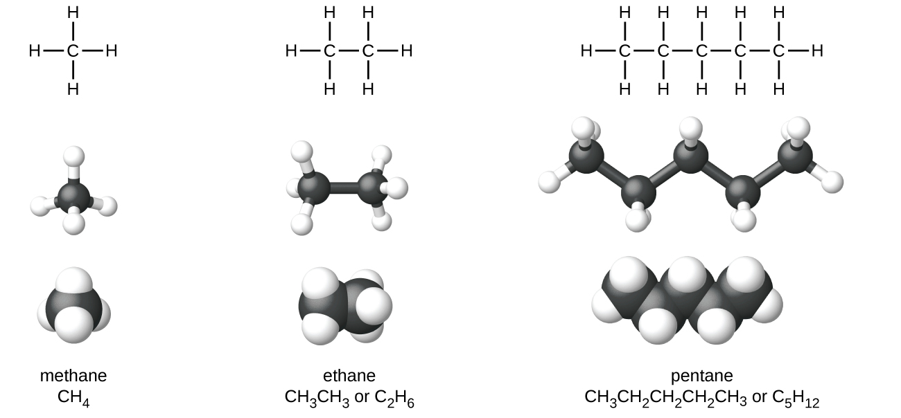
The figure illustrates four ways to represent molecules for molecules of methane, ethane, and pentane. In the first row of the figure, Lewis structural formulas show element symbols and bonds between atoms. Methane has a central C atom with four H atoms bonded to it. Ethane has a C atom with three H atoms bonded to it. The C atom is also bonded to another C atom with three H atoms bonded to it. Pentane has a C atom with three H atoms bonded to it. The C atom is bonded to another C atom with two H atoms bonded to it. The C atom is bonded to another C atom with two H atoms bonded to it. The C atom is bonded to another C atom with two H atoms bonded to it. The C atom is bonded to another C atom with three H atoms bonded to it. In the second row, ball-and-stick models are shown. In these representations, bonds are represented with sticks, and elements are represented with balls. Carbon atoms are black and hydrogen atoms are white in this image. In the third row, space-filling models are shown. In these models, atoms are enlarged and pushed together, without sticks to represent bonds. The molecule names and structural formulas are provided in the fourth row. Methane is named and represented with a condensed structural formula as C H subscript 4. Ethane is named and represented with two structural formulas C H subscript 3 C H subscript 3 and C subscript 2 H subscript 6. Pentane is named and represented as both C H subscript 3 C H subscript 2 C H subscript 2 C H subscript 2 C H subscript 3 and C subscript 5 H subscript 12.
Figure 17. Pictured are the Lewis structures, ball-and-stick models, and space-filling models for molecules of methane, ethane, and pentane.

A common method to simplify the drawings of larger molecules is to use a skeletal structure (also called a line-angle structure). In this type of structure, carbon atoms are not symbolized with a C, but represented by each end of a line or bend in a line. Hydrogen atoms are not drawn if they are attached to a carbon. Other atoms besides carbon and hydrogen are represented by their elemental symbols. Figure 18 shows three different ways to draw the same structure.
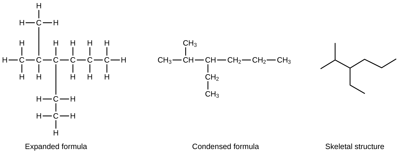
In this figure, a hydrocarbon molecule is shown in three ways. First, an expanded formula shows all individual carbon atoms, hydrogen atoms, and bonds in a branched hydrocarbon molecule. An initial C atom is bonded to three H atoms. The C atom is bonded to another C atom in the chain. This second C atom is bonded to one H atom and another C atom above the chain. The C atom bonded above the second C atom in the chain is bonded to three H atoms. The second C atom in the chain is bonded to a third C atom in the chain. This third C atom is bonded to on H atom and another C atom below the chain. This C atom is bonded to two H atoms and another C atom below the chain. This second C atom below the chain is bonded to three H atoms. The third C atom in the chain is bonded to a fourth C atom in the chain. The fourth C atom is bonded to two H atoms and a fifth C atom. The fifth C atom is bonded to two H atoms and a sixth C atom. The sixth C atom is bonded to three H atoms. Second, a condensed formula shows each carbon atom of the molecule in clusters with the hydrogen atoms bonded to it, leaving C H, C H subscript 2, and C H subscript 3 groups with bonds between them. The structure shows a C H subscript 3 group bonded to a C H group. The C H group is bonded above to a C H subscript 3 group. The C H group is also bonded to another C H group. This C H group is bonded to a C H subscript 2 group below and a C H subscript 3 group below that. This C H group is also bonded to a C H subscript 2 group which is bonded to another C H subscript 2 group. This C H subscript 2 group is bonded to a final C H subscript 2 group. The final structure in the figure is a skeletal structure which includes only line segments arranged to indicate the structure of the molecule.
Figure 18. The same structure can be represented three different ways: an expanded formula, a condensed formula, and a skeletal structure.

Example 5

Drawing Skeletal Structures
Draw the skeletal structures for these two molecules:
Figure a shows a branched molecule with C H subscript 3 bonded to C with C H subscript 3 groups bonded both above and below it. To the right of the central C, a C H is bonded which has a C H subscript 3 group bonded above and to the right and below and to the right. Figure b shows a straight chain molecule composed of C H subscript 3 C H subscript 2 C H subscript 2 C H subscript 2 C H subscript 2 C H subscript 2 C H subscript 3.

Solution
Each carbon atom is converted into the end of a line or the place where lines intersect. All hydrogen atoms attached to the carbon atoms are left out of the structure (although we still need to recognize they are there):
Figure a shows a branched skeleton structure that looks like a plus sign with line segments extending up and to the right and down and to the left of the rightmost point of the plus sign. Figure b appears in a zig zag pattern made with six line segments. The segments rise, fall, rise, fall, rise, and fall moving left to right across the figure.

Check Your Learning
Draw the skeletal structures for these two molecules:
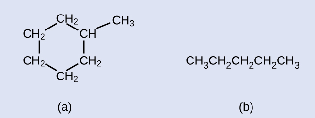
Figure a shows five C H subscript 2 groups and one C H group bonded in a hexagonal ring. A C H subscript 3 group appears above and to the right of the ring, bonded to the ring on the C H group appearing at the upper right portion of the ring. In b, a straight chain molecule composed of C H subscript 3 C H subscript 2 C H subscript 2 C H subscript 2 C H subscript 3 is shown.

Answer:
In a, a hexagon with a vertex at the top is shown. The vertex just to the right has a line segment attached that extends up and to the right. In b, a zig zag pattern is shown in which line segments rise, fall, rise, fall, and rise moving left to right.

Example 6

Interpreting Skeletal Structures
Identify the chemical formula of the molecule represented here:
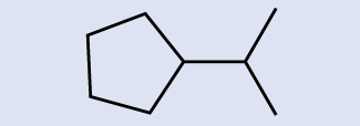
This figure shows a pentagon with a vertex pointing right, from which a line segment extends that has two line segments attached at its right end, one extending up and to the right, and the other extending down and to the right.

Solution
There are eight places where lines intersect or end, meaning that there are eight carbon atoms in the molecule. Since we know that carbon atoms tend to make four bonds, each carbon atom will have the number of hydrogen atoms that are required for four bonds. This compound contains 16 hydrogen atoms for a molecular formula of C8H16.

Location of the hydrogen atoms:
In this figure a ring composed of four C H subscript 2 groups and one C H group in a pentagonal shape is shown. From the C H group, which is at the right side of the pentagon, a C H is bonded. From this C H, a C H subscript 3 group is bonded above and to the right and a second is bonded below and to the right.

Check Your Learning
Identify the chemical formula of the molecule represented here:
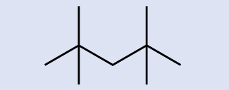
A skeleton model is shown with a zig zag pattern that rises, falls, rises, and falls again left to right through the center of the molecule. From the two risen points, line segments extend both up and down, creating four branches.

Answer:

C9H20

Constitutional Isomers

Hydrocarbons with the same formula can have different structures. For example, alkanes with the formula C4H10 can have the following Lewis structures, and are called n-butane and 2-methylpropane (or isobutane).The figure illustrates three ways to represent molecules of n dash butane and 2 dash methlylpropane. In the first row of the figure, Lewis structural formulas show element symbols and bonds between atoms. The n dash butane molecule shows 4 carbon atoms represented by the letter C bonded in a straight horizontal chain with hydrogen atoms represented by the letter H bonded above and below all carbon atoms. H atoms are bonded at the ends to the left and right of the left-most and right-most C atoms. In the second row, ball-and-stick models are shown. In these representations, bonds are represented with sticks, and elements are represented with balls. Carbon atoms are black and hydrogen atoms are white in this image. In the third row, space-filling models are shown. In these models, atoms are enlarged and pushed together, without sticks to represent bonds. The molecule names are provided in the fourth row.
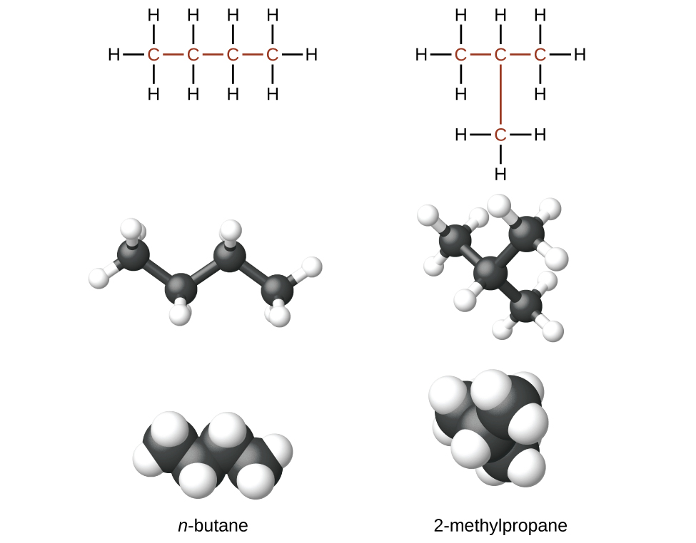
The two compounds are structural isomers (or constitutional isomers). Constitutional isomers have the same molecular formula but different spatial arrangements of the atoms. They differ from one another in one or more physical properties, such as boiling point, solubility, chemical reactivity, etc. The n-butane molecule contains an unbranched chain, meaning that no carbon atom is bonded to more than two other carbon atoms. We use the term normal, or the prefix n, to refer to a chain of carbon atoms without branching. The compound 2–methylpropane has a branched chain (the carbon atom in the center of the Lewis structure is bonded to three other carbon atoms).

Identifying isomers from Lewis structures is not as easy as it looks. Lewis structures that look different may actually represent the same isomers. For example, the three structures in Figure 19 all represent the same molecule, n-butane, and hence are not different isomers. They are identical because each contains an unbranched chain of four carbon atoms.

The figure illustrates three ways to represent molecules of n dash butane. Lewis structural formulas show carbon and hydrogen element symbols and bonds between the atoms. The first structure in the row shows three of the linked C atoms in a horizontal row with a single C atom bonded above the left-most carbon. The left-most C atom has two H atoms bonded to it. The C atom bonded above the left-most C atom has three H atoms bonded to it. The C atom bonded to the right of the left-most C atom has two H atoms bonded to it. The right-most C atom has three H atoms bonded to it. The C atoms and the bonds connecting all the C atoms are red. The second structure in the row similarly shows the row of three linked C atoms with a single C atom bonded below the C atom to the left. The left-most C atom has two H atoms bonded to it. The C atom bonded below the left-most C atom has three H atoms bonded to it. The C atom bonded to the right of the left-most C atom has two H atoms bonded to it. The right-most atom has three H atoms bonded to it. All the C atoms and the bonds between them are red. The third structure has two C atoms bonded in a row with a third C atom bonded above the left C atom and the fourth C atom bonded below the right C atom. The C atom bonded above the left C atom has three H atoms bonded to it. The left C atom has two H atoms bonded to it. The right C atom has two H atoms bonded to it. The C atom bonded below the right C atom has three H atoms bonded to it. All the C atoms and the bonds between them are red.
Figure 19. These three representations of the structure of n-butane are not isomers because they all contain the same arrangement of atoms and bonds.

Cyclic Alkanes

Cycloalkanes are characterized by a ring of carbon atoms. If a hydrocarbon chain is to be made into a ring, a new C—C bond must be formed between carbon atoms at the end of the chain. This requires that two hydrogen atoms be removed to make room for the new bond. Consequently such a ring involves one more C—C bond and two less C—H bonds than the corresponding normal alkane. Cycloalkanes containing one ring have a general formula of CnH2n, with two less hydrogen atoms than the linear alkane with the same number of carbon atoms. We refer to this reduction in number of hydrogen atoms as degree of unsaturation, which indicates the total number of rings and π bonds present in a molecule. 1 degree of unsaturation corresponding to having two less hydrogen atoms.

The most common cycloalkane in petroleum is methylcyclohexane:
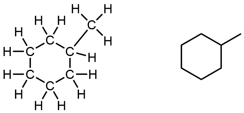

A ball-and-stick model of one of the conformations of methylcyclohexane is shown  below. Note that the ring of six carbon atoms is puckered, and does not line in a flat plane.
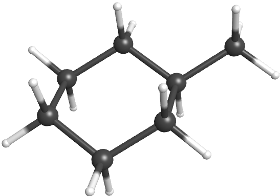
Ch4.9 Alkenes

Organic compounds that contain one or more double or triple bonds between carbon atoms are unsaturated. You have likely heard of unsaturated fats. These are complex organic molecules with long chains of carbon atoms containing at least one double bond between carbon atoms. Unsaturated hydrocarbon molecules that contain one or more double bonds are called alkenes. Carbon atoms linked by a double bond are bound together by two bonds, one σ bond and one π bond. The general formula for alkenes with one double bond is CnH2n. It has two less hydrogen atoms than the corresponding alkane, and hence 1 degree of unsaturation.

The name of an alkene is derived from the name of the alkane with the same number of carbon atoms. The presence of the double bond is signified by replacing the suffix -ane with the suffix -ene. Ethene, C2H4, commonly called ethylene, is the simplest alkene. The second member of the series is propene (propylene), C3H6. The butene isomers follow in the series. The four carbon atoms in the chain of butene give rise to different constitutional isomers based on the position of the double bond. The location of the double bond is identified by the smaller of the number of the carbon atoms participating in the double bond.
Four structural formulas and names are shown. The first shows two red C atoms connected by a red double bond illustrated with two parallel line segments. H atoms are bonded above and below to the left of the left-most C atom. Two more H atoms are similarly bonded to the right of the C atom on the right. Beneath this structure the name ethene and alternate name ethylene are shown. The second shows three C atoms bonded together with a red double bond between the red first and second C atoms moving left to right across the three-carbon chain. H atoms are bonded above and below to the left of the C atom to the left. A single H is bonded above the middle C atom. Three more H atoms are bonded above, below, and to the right of the third C atom. Beneath this structure the name propene and alternate name propylene is shown. The third shows four C atoms bonded together, numbered one through four moving left to right with a red double bond between the red first and second carbon in the chain. H atoms are bonded above and below to the left of the C atom to the left. A single H is bonded above the second C atom. H atoms are bonded above and below the third C atom. Three more H atoms are bonded above, below, and to the right of the fourth C atom. Beneath this structure the name 1 dash butene is shown. The fourth shows four C atoms bonded together, numbered one through four moving left to right with a red double bond between the red second and third C atoms in the chain. H atoms are bonded above, below, and to the left of the left-most C atom. A single H atom is bonded above the second C atom. A single H atom is bonded above the third C atom. Three more H atoms are bonded above, below, and to the right of the fourth C atom. Beneath this structure the name 2 dash butene is shown.

Isomers of Alkenes

Molecules of 1-butene and 2-butene are constitutional or structural isomers; the arrangement of the atoms in these two molecules differs. For example, the first carbon atom in 1-butene is bonded to two hydrogen atoms; the first carbon atom in 2-butene is bonded to three hydrogen atoms.

2-butene has a second type of isomerism called geometric isomer. In a set of geometric isomers, the same types of atoms are attached to each other in the same order, but the geometries of the two molecules differ. Geometric isomers of alkenes differ in the orientation of the groups on either side of a C=C bond. Carbon atoms are free to rotate around a single bond, but not around a rigid double bond. This makes it possible to have two isomers of 2-butene, one with both methyl groups on the same side of the double bond, called a cis-isomer, and one with the methyl groups on opposite sides, called a trans-isomer. These different geometries produce different physical properties, such as boiling point, that may make separation of geometric isomers possible.
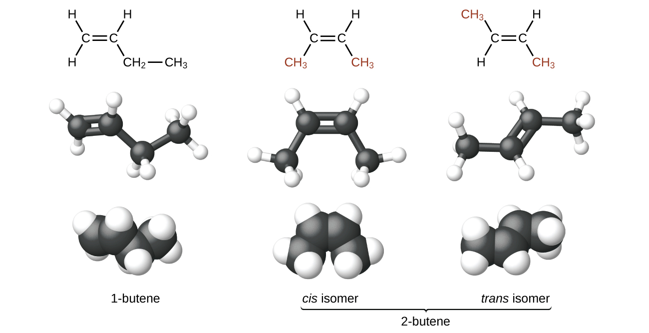
The figure illustrates three ways to represent isomers of butene. In the first row of the figure, Lewis structural formulas show carbon and hydrogen element symbols and bonds between the atoms. The first structure in this row shows a C atom with a double bond to another C atom which is bonded down and to the right to C H subscript 2 which, in turn, is bonded to C H subscript 3. The first C atom, moving from left to right, has two H atoms bonded to it and the second C atom has one H atom bonded to it. The second structure in the row shows a C atom with a double bond to another C atom. The first C atom is bonded to an H atom up and to the left and C H subscript 3 down and to the left. The second C atom is bonded to an H atom up and to the right and C H subscript 3 down and to the right. Both C H subscript 3 structures appear in red. The third structure shows a C atom with a double bond to another C atom. The first C atom from the left is bonded up to a the left to C H subscript 3 which appears and red. It is also bonded down and to the left to an H atom. The second C atom is bonded up and to the right to an H atom and down and to the left to C H subscript 3 which appears in red. In the second row, ball-and-stick models for the structures are shown. In these representations, single bonds are represented with sticks, double bonds are represented with two parallel sticks, and elements are represented with balls. C atoms are black and H atoms are white in this image. In the third row, space-filling models are shown. In these models, atoms are enlarged and pushed together, without sticks to represent bonds. In the final row, names are provided. The molecule with the double bond between the first and second carbons is named 1 dash butene. The two molecules with the double bond between the second and third carbon atoms is called 2 dash butene. The first model, which has both C H subscript 3 groups beneath the double bond is called the cis isomer. The second which has the C H subscript 3 groups on opposite sides of the double bond is named the trans isomer.
Figure 20. These molecular models show the structural and geometric isomers of butene.

Alkenes are much more reactive than alkanes because the C=C moiety is a reactive functional group. A π bond, being a weaker bond, is disrupted much more easily than a σ bond. Thus, alkenes undergo a characteristic reaction in which the π bond is broken and replaced by two σ bonds. This reaction is called an addition reaction. For example, halogens add to the double bond in an alkene:
This diagram illustrates the reaction of ethene and C l subscript 2 to form 1 comma 2 dash dichloroethane. In this reaction, the structural formula of ethane is shown. It has a double bond between the two C atoms with two H atoms bonded to each C atom plus C l bonded to C l. This is shown on to the left of an arrow. The two C atoms and the double bond between them are shown in red. To the right of the arrow, the 1 comma 2 dash dichloroethane molecule is shown. It has only single bonds and each C atom has a C l with three pairs of electron dots bonded beneath it. The C and C l atoms, single bond between them, and electron pairs are shown in red. Each C atom also has two H atoms bonded to it.

Example 7

Alkene Reactivity and Naming
Provide the IUPAC names for the reactant and product of the halogenation reaction shown here:
The left side of a reaction and arrow are shown with an empty product side. On the left, C H subscript 3 is bonded down and to the right to C H which has a double bond to another C H. The second C H is bonded up and to the right to C H subscript 2 which is also bonded to C H subscript 3. A plus sign is shown with a C l atom bonded to a C l atom following it. This is also followed by a reaction arrow.

Solution
The reactant is a five-carbon chain that contains a carbon-carbon double bond, so the base name will be pentene. We begin counting at the end of the chain closest to the double bond—in this case, from the left—the double bond spans carbons 2 and 3, so the name becomes 2-pentene. Since there are two carbon-containing groups attached to the two carbon atoms in the double bond—and they are on the same side of the double bond—this molecule is the cis-isomer, making the name of the starting alkene cis-2-pentene. The product of the halogenation reaction will have two chlorine atoms attached to the carbon atoms that were a part of the carbon-carbon double bond:
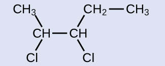
C H subscript 3 is bonded down and to the right to C H which is bonded down and to the left to C l. C H is also bonded to another C H which is bonded down and to the right to C l and up and to the right to C H subscript 2. C H subscript 2 is also bonded to C H subscript 3.

This molecule is now a substituted alkane and will be named as such. The base of the name will be pentane. We will count from the end that numbers the carbon atoms where the chlorine atoms are attached as 2 and 3, making the name of the product 2,3-dichloropentane.

Check Your Learning
What is the product of the reaction shown:
This shows a C atom bonded to three H atoms and another C atom. This second C atom is bonded to two H atoms and a third C atom. This third C atom is bonded to one H atom and also forms a double bond with a fourth C atom. This fourth C atom is bonded to one H atom and a fifth C atom. This fifth C atom is bonded to two H atoms and a sixth C atom. This sixth C atom is bonded to three H atoms. There is a plus sign followed by a C l atom bonded to another C l atom. There is a reaction arrow. no products are shown.

Answer:

3,4-dichlorohexane (can draw the product instead of using its name)

Ch4.10 Alkynes

Hydrocarbon molecules with one or more triple bonds are called alkynes; they make up another series of unsaturated hydrocarbons. Two carbon atoms joined by a triple bond are bound together by one σ bond and two π bonds. The general formula for alkynes with one triple bond is CnH2n-2. It has four less hydrogen atoms than the corresponding alkane, and hence 2 degrees of unsaturation.

The IUPAC nomenclature for alkynes is similar to that for alkenes except that the suffix -yne is used to indicate a triple bond in the chain. The simplest member of the alkyne series is ethyne, C2H2, commonly called acetylene. The Lewis structure for ethyne is:
The structural formula and name for ethyne, also known as acetylene, are shown. In red, two C atoms are shown with a triple bond illustrated by three horizontal line segments between them. Shown in black at each end of the structure, a single H atom is bonded.

Chemically, the alkynes are similar to the alkenes. Since the C≡C functional group has two π bonds, alkynes typically react even more readily, and react with twice as much reagent in addition reactions. The reaction of acetylene with bromine is a typical example:
This diagram illustrates the reaction of ethyne and two molecules of B r subscript 2 to form 1 comma 1 comma 2 comma 2 dash tetrabromoethane. In this reaction, the structural formula of ethyne, an H atom bonded to a red C atom with a red triple bond to another red C atom bonded to a black H atom, plus B r bonded to B r plus B r bonded to B r is shown to the left of an arrow. On the right, the form 1 comma 1 comma 2 comma 2 dash tetrabromoethane molecule is shown. It has an H atom bonded to a C atom which is bonded to another C atom which is bonded to an H atom. Each C atom is bonded above and below to a B r atom. Each B r atom has three pairs of electron dots. The C and B r atoms, single bond between them, and electron pairs are shown in red.


  1. This is the Beilstein database, now available through the Reaxys site (www.elsevier.com/online-tools/reaxys).
  2. Peplow, Mark. “Organic Synthesis: The Robo-Chemist,” Nature 512 (2014): 20–2.

License

Icon for the Creative Commons Attribution-NonCommercial-ShareAlike 4.0 International License

Chemistry 109 Copyright © by John Moore; Jia Zhou; and Etienne Garand is licensed under a Creative Commons Attribution-NonCommercial-ShareAlike 4.0 International License, except where otherwise noted.

Share This Book