Additional Reading Materials
Chapter 5: Molecular Bonds
Ch5.1 Covalent Bonds: Bond Length
Bond length is defined as the distance between the nuclei of two covalently bonded atoms. It is in part influenced by the number of bonded electrons (the bond order): the higher the bond order, the stronger the pull between the two atoms and the shorter the bond length. Therefore, bond length increases in the following order: triple bond < double bond < single bond. The bond length is also influenced by the covalent radii of the two atoms. You can roughly estimate the length of a single covalent bond by the sum of the two atoms' radii. Because the bond length is proportional to the atomic radius, the bond length trends in the periodic table follow the same trends as atomic radii: bond length decreases across a period and increases down a group.
The exact bond length in a diatomic molecule is determined by the distance at which the lowest potential energy is achieved as the two atoms approach each other. For example, see Figure 1 in Chapter 4.
Ch5.2 Bond Strength: Covalent Bonds
A bond’s strength describes how strongly two atoms are joined. We measure the strength of a covalent bond by the energy required to break it, that is, the energy necessary to separate the bonded atoms. Separating any pair of bonded atoms requires energy. The stronger a bond, the greater the energy required to break it.
The energy required to break a specific covalent bond in one mole of gaseous molecules is called the bond energy or the bond dissociation energy. The bond energy for a diatomic molecule, EX–Y, is defined as the standard enthalpy change for the reaction:
XY(g) → X(g) + Y(g) EX-Y = ΔHº
For example, the bond energy of the covalent H–H bond, DH–H, is 436 kJ per mole of H–H bonds broken:
H2(g) → 2H(g) EH-H = ΔHº = 436 kJ/mol
Molecules with three or more atoms have two or more bonds. The sum of all bond energies in such a molecule is equal to the standard enthalpy change for the reaction that breaks all the bonds in the molecule. For example, the sum of the four C–H bond energies in CH4 is 1660 kJ/mol:

The average C–H bond energy, EC–H, is 1660/4 = 415 kJ/mol because there are four moles of C–H bonds broken per mole of the reaction. Although the four C–H bonds are equivalent in the original molecule, they do not each require the same energy to break; once the first bond is broken (which requires 439 kJ/mol), the remaining bonds are easier to break. The 415 kJ/mol value is the average, not the exact value required to break any one bond.
The strength of a bond between two atoms increases as the number of electron pairs in the bond increases. Generally, as the bond strength increases, the bond length decreases. Thus, we find that triple bonds are stronger and shorter than double bonds between the same two atoms; likewise, double bonds are stronger and shorter than single bonds between the same two atoms. Average bond energies for some common bonds are listed in the appendix, and a comparison of bond lengths and bond strengths for some common bonds is in Table 1. The bond strength typically decreases as we move down the group. For example, C–F is 485 kJ/mol, C–Cl is 327 kJ/mol, and C–Br is 285 kJ/mol.
| Bond | Bond Length (Å) | Bond Energy (kJ/mol) |
|---|---|---|
| C–C | 1.54 | 356 |
| C=C | 1.34 | 598 |
| C≡C | 1.21 | 813 |
| C–N | 1.47 | 285 |
| C=N | 1.27 | 616 |
| C≡N | 1.15 | 866 |
| C–O | 1.43 | 336 |
| C=O | 1.21 | 695 |
| C≡O | 1.13 | 1073 |
| Table 1. Average Bond Lengths and Bond Energies for Some Common Bonds | ||
We can use bond energies to calculate approximate enthalpy changes for reactions. The enthalpy change, ΔH, for a chemical reaction is approximately equal to the sum of the energy required to break all bonds in the reactants (energy “in”, positive sign) plus the energy released when all bonds are formed in the products (energy “out,” negative sign). This can be expressed mathematically in the following way:
ΔH = ∑Ebonds broken - ∑Ebonds formed
In calculating enthalpies in this manner, it is important that we consider the bonding in all reactants and products. Because E values are typically averages for one type of bond in many different molecules, this calculation provides a rough estimate, not an exact value, for the enthalpy of reaction.
Consider the following reaction:
H2(g) + Cl2(g) → 2HCl(g)
To form two moles of H-Cl bonds(bond energy = 431 kJ/mol), one mole of H–H bonds (436 kJ/mol) and one mole of Cl–Cl bonds are broken(242 kJ/mol).
[latex]\begin{array}{r @{{}={}} l} \Delta H & \sum{\text{E}_{\text{bonds broken}}} - \sum{\text{E}_{\text{bonds formed}}} \\[1em] & [\text{E}_{\text{H} - \text{H}} + \text{E}_{\text{Cl} - \text{Cl}}] - 2\text{E}_{\text{H} - \text{Cl}} \\[1em] & [436\;\text{kJ/mol} + 242\;\text{kJ/mol}] - 2(431\;\text{kJ/mol}) \\[1em] & - 184\;\text{kJ/mol} \end{array}[/latex]
Because the bonds in the products are stronger than those in the reactants, the reaction releases more energy than it consumes. This excess energy is released as heat.
Example 1
Using Bond Energies to Calculate Approximate Enthalpy Changes
Methanol, CH3OH, may be an excellent alternative fuel. The high-temperature reaction of steam and carbon produces a mixture of the gases carbon monoxide, CO, and hydrogen, H2, from which methanol can be produced. Using the bond energies in the appendix, calculate the approximate enthalpy change, ΔH, for the reaction:
Solution
First, we need to write the Lewis structures of the reactants and the products:

From this, we see that this reaction involves breaking a C–O triple bond and two H–H single bonds, as well as the energy produced by the formation of three C–H single bonds, a C–O single bond, and an O–H single bond. We can express this as follows:
ΔH = [EC≡O + 2(EH-H)] - [3(EC-H) + EC-O + EO-H]
Using the bond energy values in the appendix, we obtain:
ΔH = [1073 kJ/mol + 2(436 kJ/mol)] - [3(416 kJ/mol) + 336 kJ/mol + 467 kJ/mol] = -106 kJ/mol
Check Your Learning
Ethyl alcohol, CH3CH2OH, was one of the first organic chemicals deliberately synthesized by humans. It has many uses in industry, and it is the alcohol contained in alcoholic beverages. It can be obtained by the fermentation of sugar or synthesized by the hydration of ethylene in the following reaction:

Using the bond energies in appendix, calculate an approximate enthalpy change, ΔH, for this reaction.
Answer:
–43 kJ/mol
Ch5.3 Bond Polarity: Covalent Bonds
If the atoms that form a covalent bond are identical, as in H2, Cl2, and other diatomic molecules, then the electrons in the bond must be shared equally. We refer to this as a pure covalent bond. Electrons shared in pure covalent bonds have an equal probability of being near each nucleus.
In the case of Cl2, each atom starts off with seven valence electrons, and each Cl shares one electron with the other, forming one covalent bond. The total number of electrons around each individual atom consists of six nonbonding electrons and two shared (i.e., bonding) electrons for eight total electrons, matching the number of valence electrons in the noble gas argon. Since the bonding atoms are identical, Cl2 has a pure covalent bond.
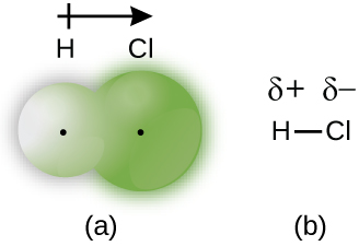
When the atoms linked by a covalent bond are different, the bonding electrons are no longer shared equally. Instead, the bonding electrons are more attracted to one atom than the other, giving rise to a shift of electron density toward that atom. This unequal distribution of electrons is known as a polar covalent bond, characterized by a partial positive charge (δ+) on the atom that attracts the electrons less strongly and a partial negative charge (δ–) on the atom that attracts the electrons more strongly. For example, the electrons in the H–Cl bond spend more time near the chlorine atom than near the hydrogen atom. Thus, in an HCl molecule, the chlorine atom carries a partial negative charge and the hydrogen atom has a partial positive charge. Figure 1 shows the distribution of electrons in the H–Cl bond, where the shaded area around Cl is much larger than it is around H.
This separation of charge gives rise to a bond dipole moment. The magnitude of a bond dipole moment is represented by the Greek letter mu (µ):
μ = Qr
where Q is the magnitude of the partial charges (determined by the electronegativity difference) and r is the distance between the charges. This bond moment can be represented as a vector, a quantity having both direction and magnitude (Figure 2). Dipole vectors are shown as arrows pointing along the bond from the less electronegative atom toward the more electronegative atom. A small plus sign is drawn on the less electronegative end to indicate the partially positive end of the bond. The length of the arrow is proportional to the magnitude of the electronegativity difference between the two atoms.

Ch5.4 Electronegativity
The polarity of a covalent bond is determined by the bonding atoms' electronegativity. Electronegativity is a measure of the tendency of an atom to attract electrons (or electron density) towards itself. It determines how the shared electrons are distributed between the two atoms in a bond. The more strongly an atom attracts the electrons in its bonds, the larger its electronegativity. Electrons in a polar covalent bond are shifted toward the more electronegative atom; thus, the more electronegative atom is the one with the δ– charge. A greater difference in electronegativity between two bonding atoms yields a more polarized electron distribution and larger partial charges on the atoms.
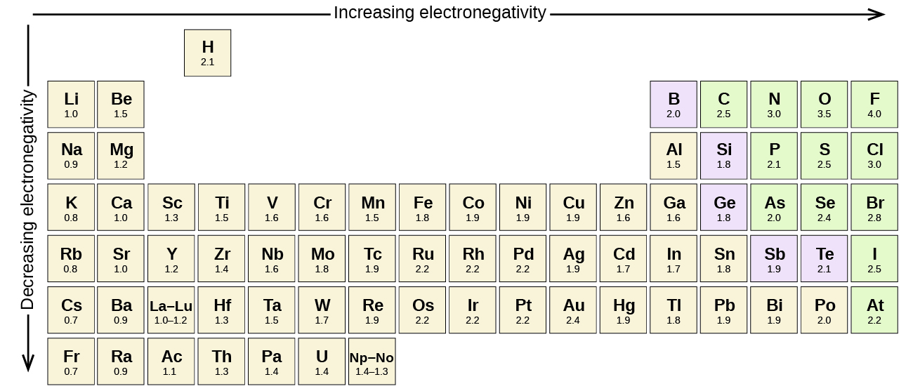
Figure 3 shows the electronegativity values of the elements as proposed by one of the most famous chemists of the twentieth century: Linus Pauling. In general, electronegativity increases from left to right across a period in the periodic table and decreases down a group. Thus, the nonmetals, which lie in the upper right, tend to have the highest electronegativities, with fluorine being the most electronegative element of all (EN = 4.0). Metals tend to be less electronegative elements, and the group 1 metals have the lowest electronegativities. Note that noble gases are excluded from this figure because these atoms usually do not share electrons with others atoms since they have a full valence shell. (While noble gas compounds such as XeO2 do exist, they can only be formed under extreme conditions, and thus they do not fit neatly into the general model of electronegativity.)
Electronegativity vs. Electron Affinity
We must be careful not to confuse electronegativity and electron affinity. The electron affinity of an element is a measurable physical quantity, namely, the energy released or absorbed when an isolated gas-phase atom acquires an electron, measured in kJ/mol. Electronegativity, on the other hand, describes how strongly an atom attracts electrons in a bond. It is a dimensionless quantity that is calculated, not measured. Pauling derived the first electronegativity values by comparing the amounts of energy required to break different types of bonds. He chose an arbitrary relative scale ranging from 0 to 4.
Linus Pauling
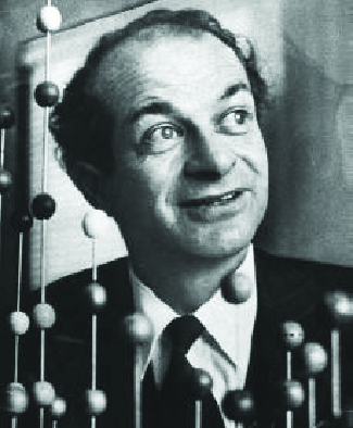
Linus Pauling, shown in Figure 4, is the only person to have received two unshared (individual) Nobel Prizes: one for chemistry in 1954 for his work on the nature of chemical bonds and one for peace in 1962 for his opposition to weapons of mass destruction. He developed many of the theories and concepts that are foundational to our current understanding of chemistry, including electronegativity and resonance structures.
Pauling also contributed to many other fields besides chemistry. His research on sickle cell anemia revealed the cause of the disease—the presence of a genetically inherited abnormal protein in the blood—and paved the way for the field of molecular genetics. His work was also pivotal in curbing the testing of nuclear weapons; he proved that radioactive fallout from nuclear testing posed a public health risk.
Electronegativity and Bond Type
The absolute value of the difference in electronegativity (ΔEN) of two bonded atoms provides a rough measure of the polarity to be expected in the bond and, thus, the bond type. When the difference is very small or zero, the bond is covalent and nonpolar. When it is large, the bond is polar covalent or ionic. The absolute values of the electronegativity differences between the atoms in the bonds H–H, H–Cl, and Na–Cl are 0 (nonpolar), 0.9 (polar covalent), and 2.1 (ionic), respectively. The degree to which electrons are shared between atoms varies from completely equal (pure covalent bonding) to not at all (ionic bonding). Figure 5 shows the relationship between electronegativity difference and bond type.
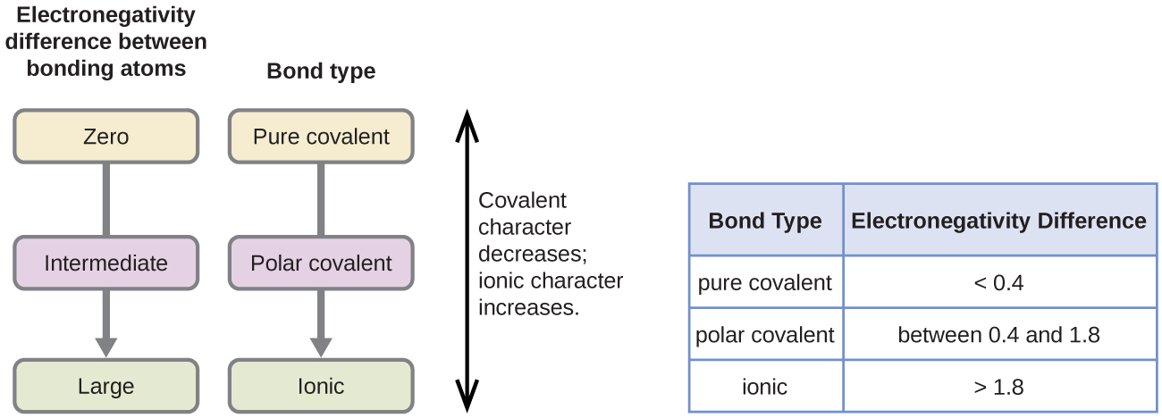
The table in Figure 5 is just a general guide, however, with many exceptions. For example, the H and F atoms in HF have an electronegativity difference of 1.9, and the N and H atoms in NH3 a difference of 0.9, yet both of these compounds form bonds that are considered polar covalent. Likewise, the Na and Cl atoms in NaCl have an electronegativity difference of 2.1, and the Mn and I atoms in MnI2 have a difference of 1.0, yet both of these substances form ionic compounds.
The best guide to the covalent or ionic character of a bond is to consider the types of atoms involved and their relative positions in the periodic table. Bonds between two nonmetals are generally covalent; bonding between a metal and a nonmetal is often ionic.
Some compounds contain both covalent and ionic bonds. The atoms in polyatomic ions, such as OH–, NO3−, and NH4+, are held together by polar covalent bonds. However, these polyatomic ions form ionic compounds by combining with ions of opposite charge. For example, potassium nitrate, KNO3, contains the K+ cation and the polyatomic NO3− anion. Thus, bonding in potassium nitrate is ionic, resulting from the electrostatic attraction between the ions K+ and NO3−, as well as covalent between the nitrogen and oxygen atoms in NO3−.
Example 2
Electronegativity and Bond Polarity
Bond polarities play an important role in determining the structure of proteins. Using the electronegativity values in the Appendix, arrange the following covalent bonds—all commonly found in amino acids—in order of increasing polarity. Then designate the positive and negative atoms using the symbols δ+ and δ–:
C–N, C–O, N–H, O–H, S–H
Solution
The polarity of these bonds increases as the absolute value of the electronegativity difference increases. The atom with the δ– designation is the more electronegative of the two.
| Bond | ΔEN | Polarity |
|---|---|---|
| S–H | 0.2 | [latex]\overset{\delta -}{\text{S}} - \overset{\delta +}{\text{H}}[/latex] |
| C–N | 0.6 | [latex]\overset{\delta +}{\text{C}} - \overset{\delta -}{\text{N}}[/latex] |
| N–H | 0.9 | [latex]\overset{\delta -}{\text{N}} - \overset{\delta +}{\text{H}}[/latex] |
| C–O | 1.0 | [latex]\overset{\delta +}{\text{C}} - \overset{\delta -}{\text{O}}[/latex] |
| O–H | 1.3 | [latex]\overset{\delta -}{\text{O}} - \overset{\delta +}{\text{H}}[/latex] |
Check Your Learning
Silicones are polymeric compounds containing, among others, the following types of covalent bonds: Si–O, Si–C, C–H, and C–C. Using the electronegativity values in the Appendix, arrange the bonds in order of increasing polarity and designate the positive and negative atoms using the symbols δ+ and δ–.
Answer:
| Bond | Electronegativity Difference | Polarity |
|---|---|---|
| C–C | 0.0 | nonpolar |
| C–H | 0.3 | [latex]\overset{\delta -}{\text{C}} - \overset{\delta +}{\text{H}}[/latex] |
| Si–C | 0.8 | [latex]\overset{\delta +}{\text{Si}} - \overset{\delta -}{\text{C}}[/latex] |
| Si–O | 1.8 | [latex]\overset{\delta +}{\text{Si}} - \overset{\delta -}{\text{O}}[/latex] |
Ch5.5 Formal Charge
The formal charge of an atom in a molecule is the hypothetical charge the atom would have if we could redistribute the electrons in the bonds evenly between the atoms. We calculate formal charge by considering the number of valence electrons of a neutral atom, subtracted by the nonbonding electrons and the number of bonds connected to that atom in the Lewis structure:
formal charge = # valence electrons in a free atom - # lone pair electrons - 0.5(# bonding electrons)
We can double-check formal charge calculation by determining the sum of the formal charges for the whole structure. The sum of the formal charges of all atoms in a neutral molecule must be zero; the sum of the formal charges in an ion should equal the charge of the ion.
The formal charge calculated for an atom is not the actual charge of the atom in the molecule. Formal charge is only a useful bookkeeping tool; it does not indicate the presence of actual charges.
Example 3
Calculating Formal Charge from Lewis Structures
Assign formal charges to each atom in the interhalogen ion ICl4−.
Solution
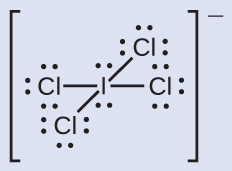
- We divide the bonding electron pairs equally for all I–Cl bonds:
- We assign lone pairs of electrons to their atoms.
- Each Cl atom now has seven electrons assigned to it, and the I atom has eight.
- Subtract this number from the number of valence electrons for the neutral atom:
- I: 7 – 8 = –1; Cl: 7 – 7 = 0. The sum of the formal charges of all the atoms equals –1, which is identical to the charge of the ion (–1).
Check Your Learning
Calculate the formal charge for each atom in the carbon monoxide molecule:

Answer:
C −1, O +1
Example 4
Calculating Formal Charge from Lewis Structures
Assign formal charges to each atom in the interhalogen molecule BrCl3.
Solution
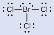
- Assign one of the electrons in each Br–Cl bond to the Br atom and one to the Cl atom in that bond:
- Assign the lone pairs to their atom.
- Now each Cl atom is assigned seven electrons and the Br atom is assigned seven electrons.
- Subtract this number from the number of valence electrons for the neutral atom.
- This gives the formal charge: Br: 7 – 7 = 0; Cl: 7 – 7 = 0. All atoms in BrCl3 have a formal charge of zero, and the sum of the formal charges totals zero, as it must be in a neutral molecule.
Check Your Learning
Determine the formal charge for each atom in NCl3.
Answer:
N: 0; all three Cl atoms: 0

Using Formal Charge to Predict Molecular Structure
The arrangement of atoms in a molecule or ion is called its molecular structure. In many cases, following the steps for writing Lewis structures may lead to more than one possible molecular structure—different multiple bond and lone-pair electron placements or different arrangements of atoms, for instance. A few guidelines involving formal charge can be helpful in deciding which of the possible structures is most likely for a particular molecule or ion:
- A molecular structure in which all formal charges are zero is preferable to one in which some formal charges are not zero.
- If the Lewis structure must have nonzero formal charges, the arrangement with the smallest nonzero formal charges is preferable.
- Lewis structures are preferable when adjacent formal charges are zero or of the opposite sign.
- When we must choose among several Lewis structures with similar distributions of formal charges, the structure with the negative formal charges on the more electronegative atoms is preferable.
To see how these guidelines apply, let us consider some possible structures for carbon dioxide, CO2. We can draw three possibilities for the structure: carbon in the center and double bonds, carbon in the center with a single and triple bond, and oxygen in the center with double bonds:

Comparing the three formal charges, we can identify the structure on the left as preferable because it has only formal charges of zero.
As another example, the thiocyanate ion, an ion formed from a C atom, a N atom, and a S atom, could have three different molecular structures: CNS–, NCS–, or CSN–. Possible Lewis structures and the formal charges for each of the three possible structures for the thiocyanate ion are shown here:

Note that the sum of the formal charges in each case is equal to the charge of the ion (–1). However, the first arrangement of atoms is preferred because it has the lowest number of atoms with nonzero formal charges. Also, it places the least electronegative atom in the center, and the negative charge on the more electronegative element.
Example 5
Using Formal Charge to Determine Molecular Structure
Nitrous oxide, N2O, commonly known as laughing gas, is used as an anesthetic in minor surgeries, such as the routine extraction of wisdom teeth. Which is the likely structure for nitrous oxide?

Solution
Determining formal charge yields the following:

The structure with a terminal oxygen atom best satisfies the criteria for the most stable distribution of formal charge:

The number of atoms with formal charges are minimized, and there is no formal charge larger than one. This is again consistent with the preference for having the less electronegative atom in the central position.
Check Your Learning
Which is the most likely molecular structure for the nitrite (NO2−) ion?

Answer:
ONO–
Ch5.6 Exceptions to the Octet Rule
Many covalent molecules have central atoms that do not have eight electrons in their Lewis structures. These molecules fall into three categories:
- Odd-electron molecules have an odd number of valence electrons, and therefore have an unpaired electron.
- Electron-deficient molecules have a central atom that has fewer electrons than needed for a noble gas configuration.
- Hypervalent molecules have a central atom that has more electrons than needed for a noble gas configuration.
Odd-electron Molecules
We call molecules that contain an odd number of electrons free radicals. Nitric oxide, NO, is such an example; it is produced in internal combustion engines when oxygen and nitrogen react at high temperatures.
To draw the Lewis structure for an odd-electron molecule like NO, we follow the same five steps we would for other molecules, but with a few minor changes:
- Determine the total number of valence (outer shell) electrons. The sum of the valence electrons is 5 (from N) + 6 (from O) = 11. The odd number immediately tells us that we have a free radical, so we know that not every atom can have eight electrons in its valence shell.
- Draw a skeleton structure of the molecule. We can easily draw a skeleton with an N–O single bond.
- Distribute the remaining electrons as lone pairs on the terminal atoms. In this case, there is no central atom, so we distribute the electrons around both atoms. We give eight electrons to the more electronegative atom in these situations; thus oxygen has the filled valence shell:

- Place all remaining electrons on the central atom. Since there are no remaining electrons, this step does not apply.
- Rearrange the electrons to make multiple bonds with the central atom in order to obtain octets wherever possible. We know that an odd-electron molecule cannot have an octet for every atom, but we want to get each atom as close to an octet as possible. In this case, nitrogen has only five electrons around it. To move closer to an octet for nitrogen, we take one of the lone pairs from oxygen and use it to form a NO double bond. (We cannot take another lone pair of electrons on oxygen and form a triple bond because nitrogen would then have nine electrons:)

Electron-deficient Molecules
We will also encounter a few molecules that contain central atoms that do not have a filled valence shell. Generally, these are molecules with central atoms from groups 2 and 12, outer atoms that are hydrogen, or other atoms that do not form multiple bonds. For example, in the Lewis structures of beryllium dihydride, BeH2, and boron trifluoride, BF3, the beryllium and boron atoms each have only four and six electrons, respectively. It is possible to draw a structure with a double bond between a boron atom and a fluorine atom in BF3, satisfying the octet rule, but experimental evidence indicates the bond lengths are closer to that expected for B–F single bonds. This suggests the best Lewis structure has three B–F single bonds and an electron deficient boron. The reactivity of the compound is also consistent with an electron deficient boron. However, the B–F bonds are slightly shorter than what is actually expected for B–F single bonds, indicating that some double bond character is found in the actual molecule.
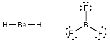
An atom like the boron atom in BF3, which does not have eight electrons, is very reactive. It readily combines with a molecule containing an atom with a lone pair of electrons. For example, NH3 reacts with BF3 because the lone pair on nitrogen can be shared with the boron atom:

Hypervalent Molecules
Elements in the second period of the periodic table (n = 2) can accommodate only eight electrons in their valence shell orbitals because they have only four valence orbitals (one 2s and three 2p orbitals). Elements in the third and higher periods (n ≥ 3) have more than four valence orbitals and can share more than four pairs of electrons with other atoms because they have empty d orbitals in the same shell. Molecules formed from these elements are sometimes called hypervalent molecules. For example, in PCl5, the central phosphorus atom shares five pairs of electrons. In SF6, sulfur shares six pairs of electrons.
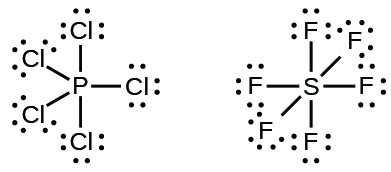
In some hypervalent molecules, such as IF5 and XeF4, some of the electrons in the outer shell of the central atom are lone pairs:

When we write the Lewis structures for these molecules, we find that we have electrons left over after filling the valence shells of the outer atoms with eight electrons. These additional electrons must be assigned to the central atom.
Example 6
Writing Lewis Structures: Octet Rule Violations
Xenon is a noble gas, but it forms a number of stable compounds. We examined XeF4 above. What are the Lewis structures of XeF2 and XeF6?
Solution
We can draw the Lewis structure of any covalent molecule by following the six steps discussed earlier. In this case, we can condense the last few steps, since not all of them apply.
- Calculate the number of valence electrons:
XeF2: 8 + (2 × 7) = 22
XeF6: 8 + (6 × 7) = 50 - Draw a skeleton joining the atoms by single bonds. Xenon will be the central atom because fluorine cannot be a central atom:
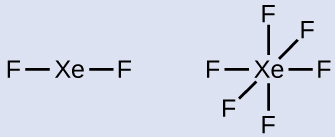
- Distribute the remaining electrons.

XeF2: We place three lone pairs of electrons around each F atom, accounting for 12 electrons and giving each F atom 8 electrons. Thus, six electrons (three lone pairs) remain. These lone pairs must be placed on the Xe atom. This is acceptable because Xe atoms have empty valence shell d orbitals and can accommodate more than eight electrons. The Lewis structure of XeF2 shows two bonding pairs and three lone pairs of electrons around the Xe atom.
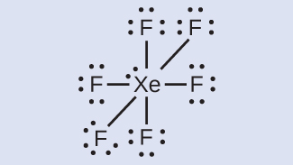
XeF6: We place three lone pairs of electrons around each F atom, accounting for 36 electrons. Two electrons remain, and this lone pair is placed on the Xe atom.
Check Your Learning
The halogens form a class of compounds called the interhalogens, in which halogen atoms covalently bond to each other. Write the Lewis structures for the interhalogens BrCl3 and ICl4−.
Answer:

Ch5.7 Resonance Structures
The nitrite anion, NO2-, can have two possible structures with the atoms in the same positions but the electrons involved in the N–O double bond in different positions:

If NO2- do indeed contain a single and a double bond, we would expect for the two bond lengths to be different. A N=O double bond is shorter (and stronger) than a N-O single bond. Experimental results show, however, that both bonds in NO2− have the same strength and length, and are identical in all other properties.
It is not possible to write a single Lewis structure for NO2− in which nitrogen has an octet and both bonds are equivalent. Instead, we use the concept of resonance structures: if two or more Lewis structures with the same arrangement of atoms can be written for a molecule, the actual distribution of electrons is a weighted average of that shown by the various Lewis structures. The actual distribution of electrons in each of the nitrogen-oxygen bonds in NO2− is the average of a double bond and a single bond. We call the individual Lewis structures resonance forms. The actual electronic structure of the molecule (the average of the resonance forms) is called a resonance hybrid of the individual resonance forms. A double-headed arrow between Lewis structures indicates that resonance forms are being depicted. Thus, the electronic structure of the NO2− ion is shown as:

A molecule described by a resonance hybrid never possesses an electronic structure shown by either resonance form. It does not fluctuate between resonance forms; rather, the actual electronic structure is always the weighted average of that shown by all resonance forms. George Wheland, one of the pioneers of resonance theory, used a historical analogy to describe the relationship between resonance forms and resonance hybrids. A medieval traveler, having never before seen a rhinoceros, described it as a hybrid of a dragon and a unicorn because it had many properties in common with both. Just as a rhinoceros is neither a dragon sometimes nor a unicorn at other times, a resonance hybrid is neither of its resonance forms at any given time. Like a rhinoceros, it is a real entity that experimental evidence has shown to exist. It has some characteristics in common with its resonance forms, but the resonance forms themselves are convenient imaginary images (like the unicorn and the dragon).
The carbonate anion, CO32−, provides another example of resonance:

One oxygen atom must have a double bond to carbon to complete the octet on the central atom. All oxygen atoms, however, are equivalent, and the double bond could form with any one of them. This gives rise to three dominant resonance forms of the carbonate ion. Because we can write three identical resonance structures, we know that the actual arrangement of electrons in the carbonate ion is the average of the three structures. Again, experiments show that all three C–O bonds are exactly the same, and are not single or double bonds, but somewhere in between. In other words, the π bond is delocalized in the molecule, as opposed to being only between one oxygen and one carbon.
When drawing resonance structures, be mindful of the following:
- Resonance structures should have the same number of electrons, do not add or subtract any electrons. (check the number of electrons by simply counting them; formal charge is quite useful here).
- Between resonance structures, atoms do not move, only the electrons move. (The skeleton of the structure can not be changed; molecule is not rotated between resonance structures).
- Use a double-headed arrow between resonance structures.
It is certainly possible to have resonance structures that have different weighting in the average. You can think of it as one resonance structure having a better description of the molecule than the others (however, none are sufficient on its own).
The online Lewis Structure Make includes many examples to practice drawing resonance structures.
Ch5.8 Aromatic Hydrocarbons
Benzene, C6H6, is the simplest member of a large family of hydrocarbons, called aromatic hydrocarbons. These compounds contain ring structures and exhibit bonding that must be described using the resonance hybrid concept or the delocalization concept of molecular orbital theory. The resonance structures for benzene, C6H6, are:
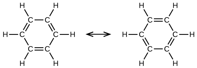
Benzene does not exhibit the characteristics typical of an alkene. For example, it will not undergo an addition reaction like a typical alkene. Each of the six bonds between its carbon atoms is equivalent and exhibits properties that are intermediate between those of a C–C single bond and a C=C double bond. To represent this unique bonding, structural formulas for benzene and its derivatives are sometimes drawn with single bonds between the carbon atoms and a circle within the ring as shown in Figure 6.
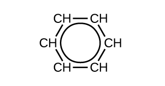
There are many derivatives of benzene. The hydrogen atoms can be replaced by many different substituents. Aromatic compounds typically undergo substitution reactions rather than addition reactions; replacement of one of the hydrogen atoms with another substituent will leave the delocalized double bonds intact. The following are some examples of substituted benzene hydrocarbon derivatives:

Toluene and xylene are important solvents and raw materials in the chemical industry. Styrene is used to produce the polymer polystyrene.
Example 7
Structure of Aromatic Hydrocarbons
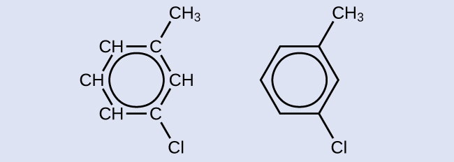
One possible isomer created by a substitution reaction that replaces a hydrogen atom attached to the aromatic ring of toluene with a chlorine atom is shown here. Draw two other possible isomers in which the chlorine atom replaces a different hydrogen atom attached to the aromatic ring:
Solution
Since the six-carbon ring with alternating double bonds is necessary for the molecule to be classified as aromatic, appropriate isomers can be produced only by changing the positions of the chloro-substituent relative to the methyl-substituent:

Check Your Learning
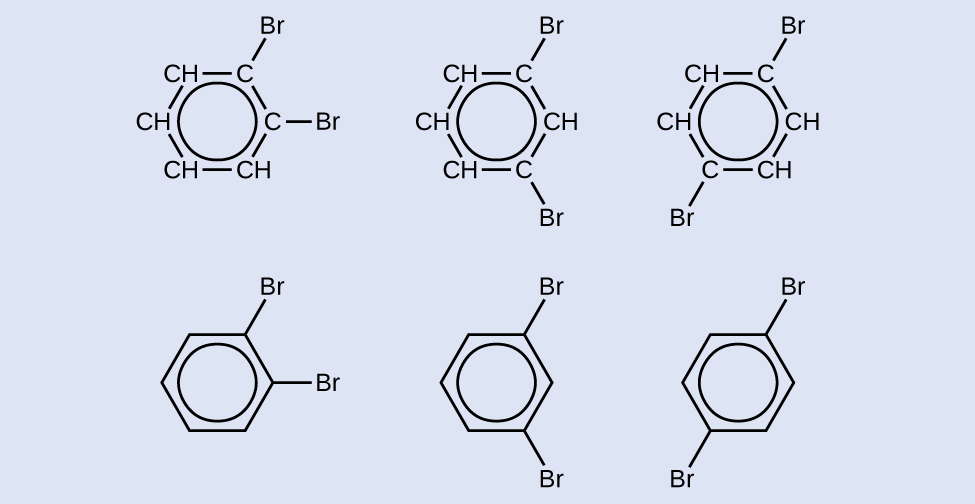
Draw three isomers of a six-membered aromatic ring compound substituted with two bromines.

