Unit Two
Day 11: Resonance Structures, VSEPR Theory
As you work through this section, if you find that you need a bit more background material to help you understand the topics at hand, you can consult “Chemistry: The Molecular Science” (5th ed. Moore and Stanitski) Chapter 6-9 and 6-11 and Chapter 7-1 through 7-2d, and/or Chapter 5.7-5.8 and 6.1-6.2 in the Additional Reading Materials section.
D11.1 Resonance Structures
In a single Lewis structure, a pair of electrons can only be depicted as shared between two atoms or localized to a single atom. However, as mentioned in Section 6.4, the MOs of a polyatomic molecule often span the entire molecule. It is useful to be able to depict such delocalized electron distributions using Lewis structures because for certain molecules the delocalization has a direct effect on molecular properties and chemical reactivity.
For example, the nitrite anion, NO2− can have two possible Lewis structures, both of which satisfy guidelines for Lewis structures and formal charges:

However, experiments show that both bonds in NO2− are identical in all properties, and the bond lengths are longer than a N=O double bond and shorter than a N-O single bond. Hence, neither Lewis structure is a complete depiction of the actual molecule, and a better representation of NO2− is an average of these two Lewis structures.
When the actual distribution of electrons is a weighted average of a set of Lewis structures, those Lewis structures are called resonance structures. The actual electronic structure of the molecule (the average of the resonance forms) is called a resonance hybrid. A double-headed arrow between Lewis structures indicates that resonance structures are being depicted:

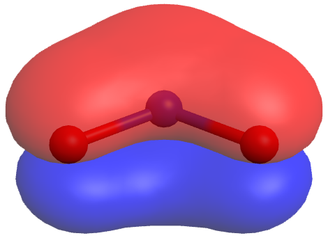
A molecule does not fluctuate between resonance structures; rather, the actual electronic structure is always the weighted average of the resonance structures. The actual NO2− molecule has a π MO that is delocalized over the entire molecule (click on the image for a rotatable 3D view):
The carbonate anion, CO32−, provides another example of resonance structures:

Experiments show that all three C–O bonds are exactly the same. In other words, the π bond is delocalized in the molecule, as opposed to being only between one oxygen and one carbon.
When drawing resonance structures, be mindful of the following:
- Resonance structures should have the same number of electrons. (Formal charge is a useful check for this.)
- Between resonance structures, atom locations are fixed, only the electrons move. (The skeleton of the structure can not be changed)
- Double-headed arrows are used between resonance structures.
In CO32−, the three major resonance structures contribute equally to the resonance hybrid. However, it is possible for some structures in a resonance hybrid to be more important than others. An example is these three resonance structures of cyanate ion (OCN–):

The atoms in each resonance structure have a full octet, but they differ in their formal charges. From the formal-charge rules, we can estimate that the resonance structure on the right would contribute the least. The resonance structure on the left would contribute more than the middle structure because it has the -1 formal charge on the more electronegative O atom. (For OCN–, high level quantum mechanics calculations show that the left structure contributes 61% to the resonance hybrid, the middle structure contributes 30%, and the right resonance structure contributes only 4%.)
Exercise 1: Identifying Resonance Structures
One Lewis structure for the thiocyanate ion is
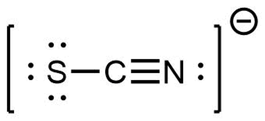
Indicate whether each structure below is an isomeric structure, a resonance structure, or neither an isomer or a resonance structure of the thiocyanate ion.
D11.2 Aromatic Molecules
Benzene, C6H6, is representative of a large number of aromatic compounds. These compounds contain ring structures and exhibit bonding that must be described using resonance structures. The resonance structures for benzene are:
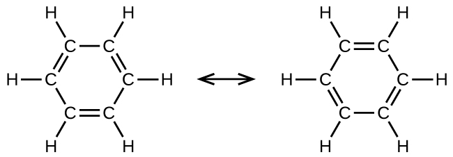
All six C-C bonds are equivalent and exhibit properties that are intermediate between those of a C–C single bond and a C=C double bond.
Aromatic compounds exhibit distinctive chemical reactivity that differs from typical alkenes. For examples, aromatic compounds do not undergo addition reactions. Instead, they can undergo substitution reactions with the aid of a catalyst, where one of the hydrogen atoms is replaced by a substituent. Such a substitution reaction would leave the delocalized double bonds intact.
Exercise 2: Isomers of Substituted Benzenes
Which of these are structural isomers of ortho-xylene?
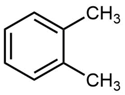
Select all that apply.
D11.3 VSEPR Theory
Lewis structures are easy-to-draw, planar representations of bonding in molecules. They tell us which atoms are bonded to which and whether bonds are single or multiple, but they don’t represent the 3D structure of a molecule nor the molecular orbitals that determine electron-density distributions. However, there is a simple procedure by which the 3D structures or most molecules can be predicted from Lewis structures without computing molecular orbitals.
Valence shell electron-pair repulsion (VSEPR) theory assumes that for each central atom in a molecule valence electrons in lone pairs and covalent bonds will minimize electron-electron repulsion by staying as far as possible from each other in 3D space. This is an oversimplification, but it works very well for many molecules. Figure 1 illustrates the electron-region geometries that minimize the repulsions between regions of high electron density. An electron region is a lone pair, a single bond, a double bond, or a triple bond. (The word “region” is used because all electrons in a bond occupy the same region of 3D space.)
- Two regions of electron density around a central atom in a molecule form a linear geometry
- Three regions form a trigonal planar geometry (trigonal means the same thing as triangular)
- Four regions form a tetrahedral geometry
- Five regions form a trigonal bipyramidal geometry (bipyramid means two pyramids linked base to base)
- Six regions form an octahedral geometry (an octahedron has eight faces, but six corners where atoms are bonded)
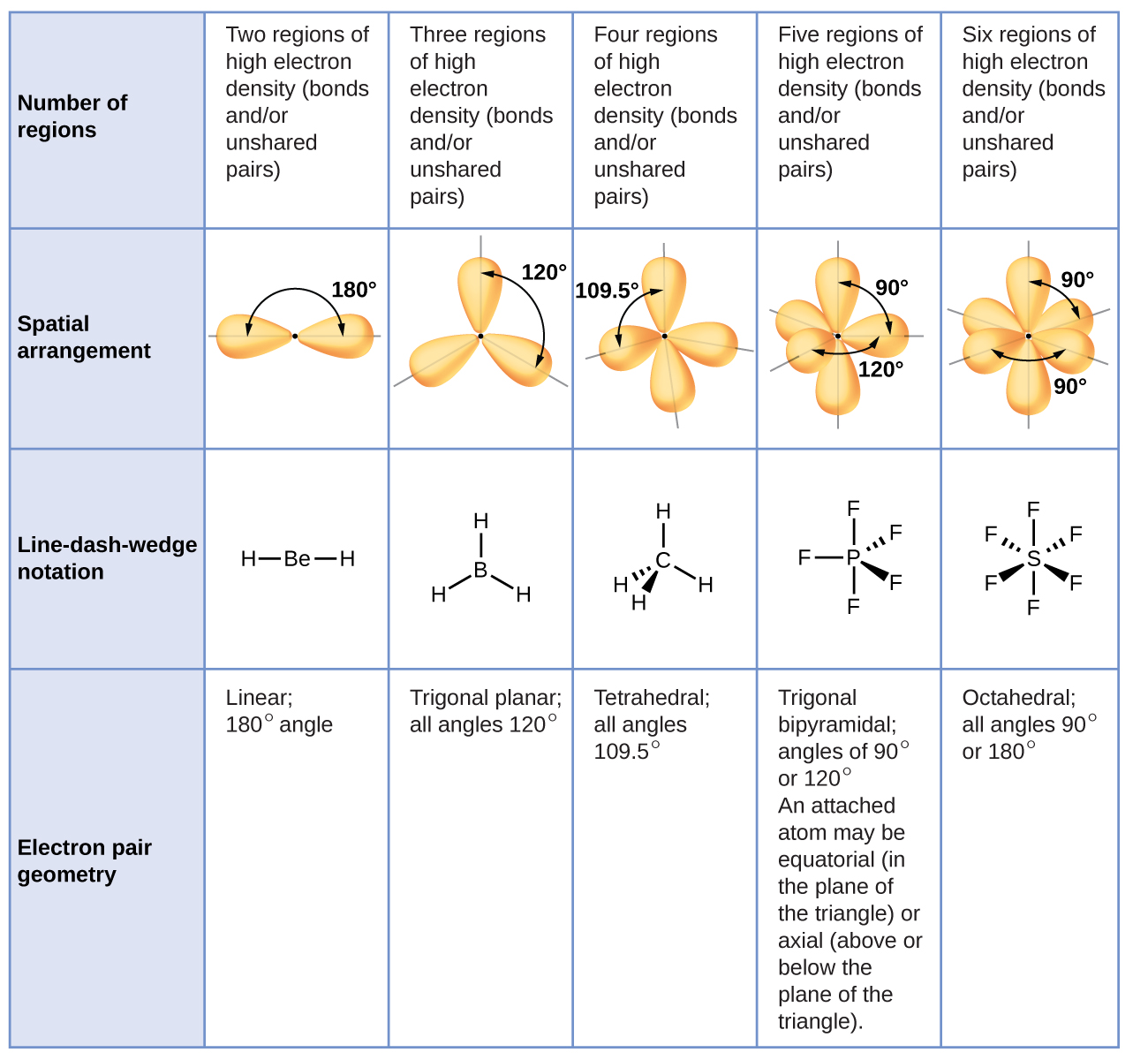
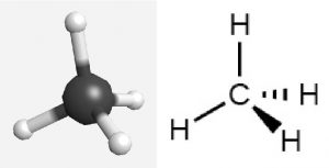
For example, methane, CH4, which is the major component of natural gas, has four bonding pairs of electrons around the central carbon atom. The largest possible angle between electron pairs is 109.5°, which is called a tetrahedral angle. Each C–H bond is 109.5° from all three other C–H bonds. The H atoms are at the four corners of a tetrahedron. A molecular model and a Lewis structure for methane look like this:
The Lewis structure above is designed to depict 3D geometry and is called wedge and dash notation. Solid lines represent bonds in the plane of the page, solid wedges represent bonds coming up in front of the plane, and dashed lines represent bonds going down behind the plane. Click on the image to see a 3D representation of the molecule, and rotate it until it looks like the depiction drawn above.
Example 1
Predicting Molecular Structure: CO2 and BCl3
Draw a wedge-dash notation structure for carbon dioxide, CO2, a molecule produced by the combustion of fossil fuels, and boron trichloride, BCl3, an important industrial chemical.
Solution
(a) Write the Lewis structure of CO2 as:

This shows us two regions of high electron density around the carbon atom—each double bond counts as one region, and there are no lone pairs on the carbon atom. VSEPR theory predicts that the two regions of electron density arrange themselves on opposite sides of the central atom with a bond angle of 180°. A CO2 molecule is linear.
(b) Write the Lewis structure of BCl3 as:
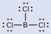
Thus, BCl3 contains three single bonds, and there are no lone pairs of electrons on boron. The arrangement of three regions of high electron density gives a trigonal planar geometry. The B–Cl bonds lie in a plane with 120° angles between them.

You can draw all three σ bonds in plane of the paper, rather than using wedge and dash as shown above. But be sure to clearly indicate the 120° angles in a trigonal planar geometry.
Check Your Learning
Carbonate, CO32−, is a common polyatomic ion found in various materials from eggshells to antacids. What is the molecular structure of this polyatomic ion?
Answer:
From any one of the three major resonance structures of CO32−: the molecular structure is trigonal planar.
Example 2
Predicting Molecular Structure: Ammonium Ion
Two of the top 50 chemicals produced in the United States, ammonium nitrate and ammonium sulfate, both used as fertilizers, contain the ammonium ion, NH4+.
Solution
Write the Lewis structure of NH4+ as:
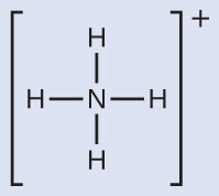
NH4+ contains four N-H single bonds and no lone pairs. The four regions of high electron density arrange themselves so that they point to the corners of a tetrahedron with the central nitrogen atom in the middle. Therefore, the molecular structure of NH4+ is tetrahedral.
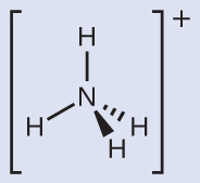
Make sure that you can properly use the wedge and dash notation to depict a correct tetrahedral arrangement.
Check Your Learning
Identify a molecule with trigonal bipyramidal molecular structure.
Answer:
Any molecule with five electron regions around the central atoms with no lone pairs will be trigonal bipyramidal. PF5 is a common example.
D11.4 Electron-Region Geometry versus Molecular Geometry
The electron-region geometry describes all regions where valence electrons are located, bonds as well as lone pairs. The molecular geometry (or molecular structure) describes the location of the atoms (that is, atomic nuclei and core electrons), not the valence electrons. The two geometries are the same only when there are no lone pairs around the central atom.
For example, ammonia, NH3, has four electron pairs associated with the central nitrogen atom, and thus has a tetrahedral electron-region geometry. One of these regions, however, is a lone pair, which is not included in the molecular geometry, and this lone pair influences the shape of the molecule (Figure 2).

VSEPR theory predicts distortions from ideal angles by approximating an order of electron-region repulsions, where:
lone pair > triple bond > double bond > single bond
Consider formaldehyde, H2CO, which is used as a preservative for biological and anatomical specimens. This molecule has three regions of high electron density: two single bonds and one double bond. The basic geometry is trigonal planar with ideal 120° bond angles, but the double bond causes slightly larger angles (121°), and the angle between the single bonds is slightly smaller (118°).
Figure 3 illustrates the molecular geometry, which are predicted based on the electron-region geometries, for various combinations of lone pairs and bonding pairs.
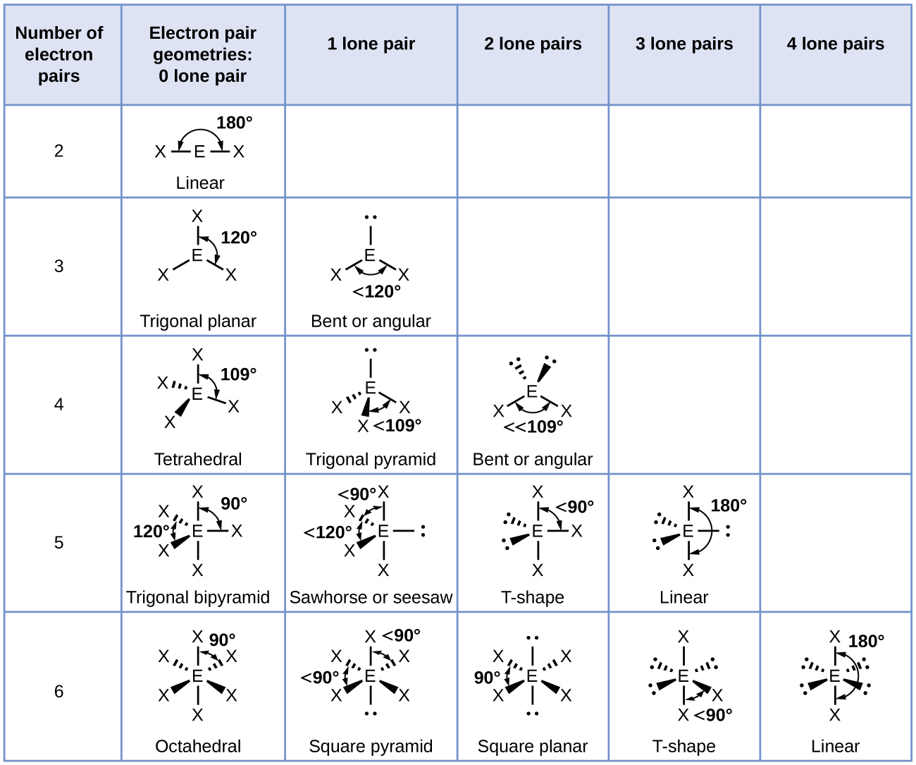
For trigonal bipyramidal geometries, there are two kinds of positions for terminal atoms (denoted as X in Figure 3): two axial positions (if we hold a model by the two axial positions, we have an axis around which we can rotate the model) and three equatorial positions (three positions around the middle of the molecule are like Earth’s equator). Each axial position is surrounded by three bond angles of 90°, whereas each equatorial position has two 90° and two 120° bond angles. The number of repulsions at the smallest bond angle predominates, so lone pairs occupy the equatorial positions.

Podia Question
View and manipulate the structure at this link to an experimentally determined structure as you answer these questions.
1. Draw the Lewis structure for formamide, CHONH2. If there are resonance structures, draw each one.
2. Use VSEPR to predict the shape of the molecule at each central atom (C and N are central atoms). If there are resonance structures, predict the shape for each structure.
3. Click the link and use the curly arrow at the upper left![]() to rotate the structure. Describe the structure. Are all atoms in the same plane?
to rotate the structure. Describe the structure. Are all atoms in the same plane?
4. Does your prediction in part 2 agree with what you see in part 3? Describe any differences.
5. Select the “adjust” tool on the left (fourth button from top![]() ). You can then click on an atom to select or deselect it. When two bonded atoms are both selected in this way, the bond length is shown at the bottom of the window. Record the carbon-nitrogen bond length, and the carbon-oxygen bond length. (Note that bond lengths are given in Ångstrom units; 1 Å = 100 pm.)
). You can then click on an atom to select or deselect it. When two bonded atoms are both selected in this way, the bond length is shown at the bottom of the window. Record the carbon-nitrogen bond length, and the carbon-oxygen bond length. (Note that bond lengths are given in Ångstrom units; 1 Å = 100 pm.)
6. Use the table of bond lengths to look up these four average bond lengths: carbon-nitrogen single bond; carbon-nitrogen double bond; carbon-oxygen single bond; carbon-oxygen double bond. Compare the observed bond lengths with the average bond lengths and predict the bond order for the carbon-nitrogen and carbon oxygen bonds in formamide. Your prediction need not be exact but it should distinguish whether each bond is single or double or something in between.
7. Does your result in part 6 correlate with the resonance structures you drew in part 1 and the shape of the molecule? Why or why not?
Two days before the next whole-class session, this Podia question will become live on Podia, where you can submit your answer.

