
M18Q4: Voltaic Cells and Standard Reduction Potential
Learning Objectives
- Quantify the electrical energy generated or used by chemical processes through calculations involving units of electric potential (volts) and electric charge (coulombs), as well as Faraday’s constant, F, (the charge of one mole of electrons).
- Describe the standard hydrogen electrode and explain how it is used as a standard to determine cell potentials of half-reactions.
Electrical Units
Electricity refers to a number of phenomena associated with the presence and flow of electric charge. The flow or movement of charge is an electric current. The SI unit of charge is the coulomb (C) and the charge of an electron is 1.602 × 10⁻¹⁹ C. The presence of an electric charge generates an electric field. Electric current is the rate of flow of charge. The SI unit for electrical current is the SI base unit called the ampere (A), which is a flow rate of 1 coulomb of charge per second (1 A = 1 C/s). An electric current flows in a path, called an electric circuit. In most chemical systems, it is necessary to maintain a closed path for current to flow. The flow of charge is generated by an electrical potential difference, or potential, between two points in the circuit. Electrical potential is the ability of the electric field to do work on the charge. The SI unit of electrical potential is the volt (V). When 1 coulomb of charge moves through a potential difference of 1 volt, it gains or loses 1 joule (J) of energy. Table 1 summarizes some of this information about electricity.
In a voltaic cell, electrons spontaneously flow from the anode (oxidation reaction) to the cathode (reduction reaction). The electromotive force (EMF) or cell potential (Ecell) in a voltaic cell results from the difference in the electrical potentials for each electrode. It is a relative measurement of the difference between the potential for the reducing agent to be oxidized and the oxidizing agent to be reduced, measured in volts (V). This can be summarized in the following equation:
Ecell = Ecathode – Eanode
Under standard conditions (1 bar for gases; 1 M for solutes, and pure solids), the equation is written as:
E°cell = Eºcathode – Eºanode
Because cell potential is potential energy per unit of charge, it is an intensive property and independent of stoichiometric coefficients
Standard Hydrogen Electrode
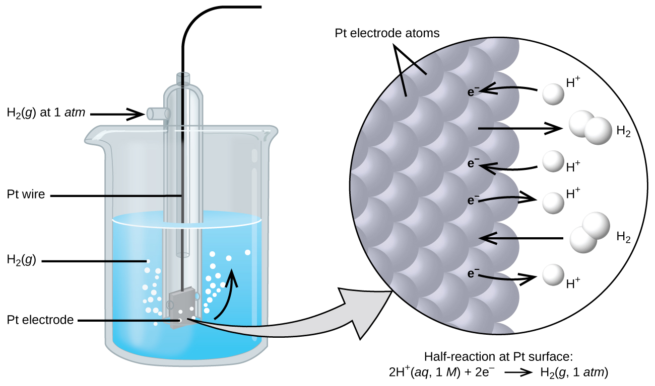
Because cell potential is the difference of potential between the two electrodes, it is impossible to determine the electrical potential of a single electrode. In order to obtain potentials for different electrodes, one electrode is assigned the value of zero and then used as a reference to assign other values. The electrode chosen as the zero is shown in Figure 1 and is called the standard hydrogen electrode (SHE). The SHE consists of 1 atm of hydrogen gas bubbled through a 1 M HCl solution, usually at room temperature, with platinum used as the electrode. The reduction half-reaction chosen as the reference is:
2 H+(aq, 1M) + 2 e– → H2(g, 1 atm) E° = 0 V
The H+/H2 half-cell voltage is defined as zero volts for all temperatures.
Assigning the potential of the standard hydrogen electrode (SHE) as zero volts allows the determination of standard reduction potentials, E°, for half-reactions in electrochemical cells. As the name implies, standard reduction potentials use standard states and are written as reduction reactions (where electrons appear on the left side of the equation). The reduction reactions are reversible, so standard cell potentials can be calculated by subtracting the standard reduction potential for the reaction at the anode from the standard reduction for the reaction at the cathode. When calculating the standard cell potential, the standard reduction potentials are not scaled by the stoichiometric coefficients in the balanced overall equation.
Using the Standard Hydrogen Electrode to find the E° for another half-reaction
A voltaic cell consisting of a SHE and Cu2+/Cu half-cell can be used to determine the standard reduction potential for Cu2+ (Figure 2).
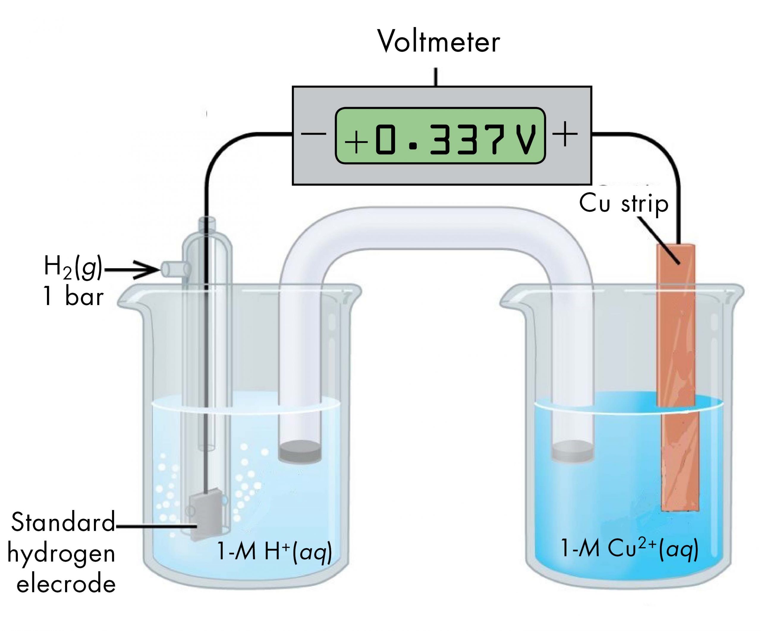
The standard reduction potential for copper can be determined by subtracting the standard reduction potential for the reaction occurring at the anode from the standard reduction potential for the reaction occurring at the cathode. The SHE is the anode on the “-” lead and copper is the cathode on the “+” lead.
E°cell = Eºcathode – Eºanode
+0.34 V = EºCu2+/Cu – EºH+/H2 = EºCu2+/Cu – 0
EºCu2+/Cu = +0.34 V
Since the measured voltage is positive, the assignments of anode and cathode are correct and electrons flow from the anode to the cathode. The reactions, which are reversible, are:
| Anode (Oxidation): | H2(g) | ⟶ | 2 H+(aq) + 2 e– |
| Cathode (Reduction): | Cu2+(aq) + 2 e– | ⟶ | Cu(s) |
| Overall: | Cu2+(aq) + H2(g) | ⟶ | 2 H+(aq) + Cu(s) |
In line notation, the reaction is:
Pt(s) | H2(g, 1 atm) | H+(aq, 1 M) || Cu2+(aq, 1 M) | Cu(s)
Likewise, a voltaic cell consisting of a SHE and Zn2+/Zn half-cell can be used to determine the standard reduction potential for Zn2+ (Figure 3).
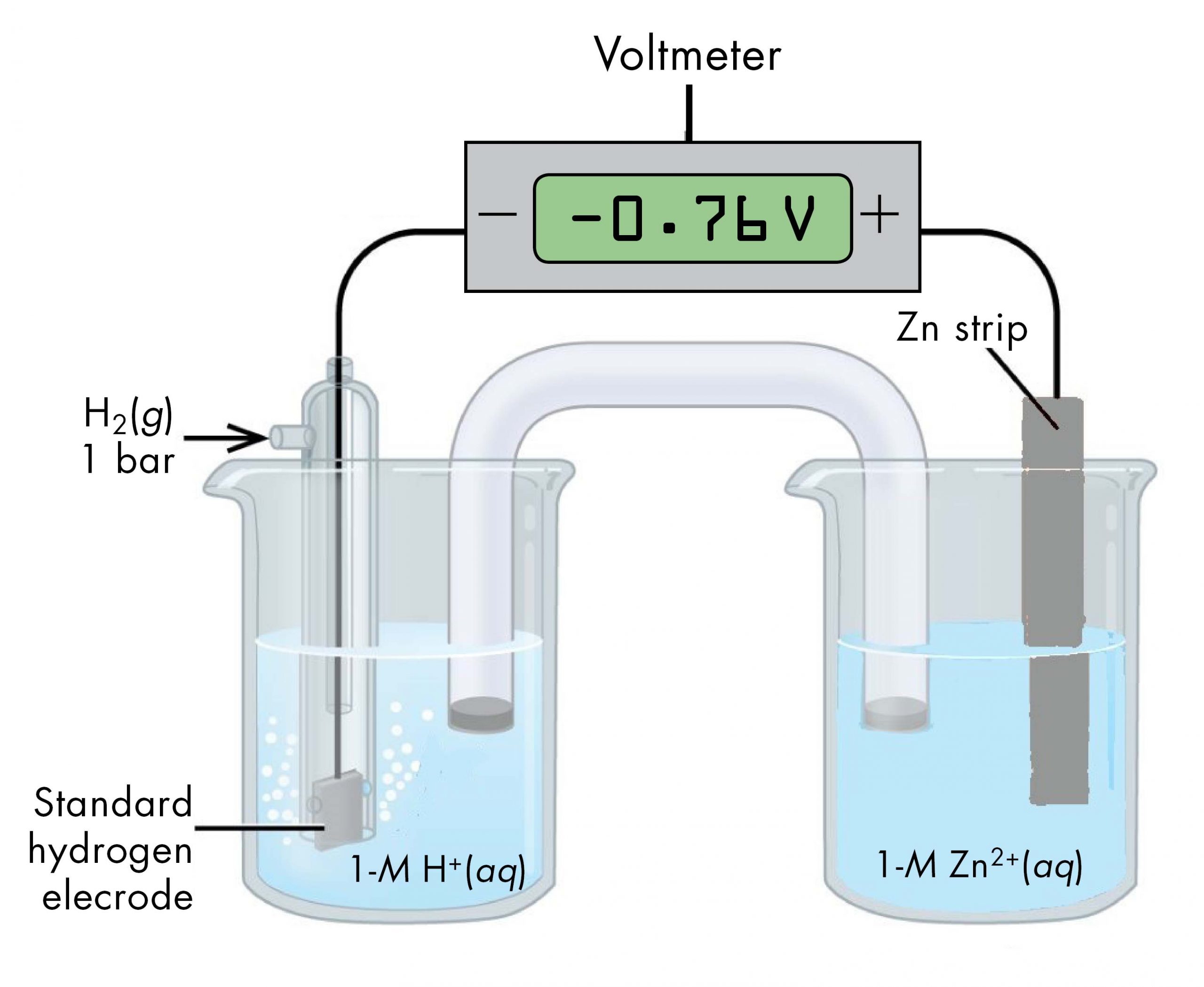
The standard reduction potential for zinc can be determined by subtracting the standard reduction potential for the reaction occurring at the anode from the standard reduction potential for the reaction occurring at the cathode. The SHE is the anode on the “-” lead and zinc is the cathode on the “+” lead.
E°cell = Eºcathode – Eºanode
-0.76 V = EºZn2+/Zn – EºH+/H2 = EºZn2+/Zn – 0
EºZn2+/Zn = -0.76 V
Since the measured voltage is negative, the leads must be flipped in order to write the spontaneous chemical reaction. Currently, the “-” lead, the anode, is attached to the SHE and the “+” lead, the cathode, is attached to the Zn. The negative voltage implies that for the spontaneous reaction, the anode is actually the Zn and the cathode is actually the SHE.
Key Concepts and Summary
Electricity is associated with the flow of electrons, typically using coulombs. This flow of electric charge creates and electric field and current, which flows on a given path (or circuit). The ability for this electric field to do work is called electric potential (or voltage), which is the basis of voltaic cells. Standard reduction potentials are used in order to predict the voltage that will be created (or if voltage will be created) between two half-cells. All half-cells are connected to a standard hydrogen electrode (SHE). The SHE is given a voltage of 0.00 V in order to be a baseline for all other half-cells. We can use the table of voltages generated through this comparison to calculate the electrical potential difference between any two electrodes using the equation, E°cell = Eºcathode – Eºanode, which always used values directly from the standard reduction potential table.
Key Equations
- E°cell = Eºcathode – Eºanode
Glossary
- cell potential
- the voltage created from the difference in the electrical potentials of the anode and cathode
- current
- the rate of flow of charge, usually in amperes (A), the flow rate of 1 coulomb of charge per second (1 A = 1 C/s)
- electric circuit
- the path of an electric current
- electrical potential
- the ability of an electric field to do work on the charge
- electromotive force (EMF)
- also known as the cell potential
- standard hydrogen electrode (SHE)
- the electrode chosen as the basis of the standard reduction potential table, which consists of 1 atm of hydrogen gas bubbled through a 1 M HCl solution, with platinum used as the inert electrode. The SHE is given a standard reduction potential of 0.00 V
- standard reduction potentials (Eº)
- the difference of electrical potential of a reduction reaction when compared to the SHE
Please use this form to report any inconsistencies, errors, or other things you would like to change about this page. We appreciate your comments. 🙂
