
M9Q1: Predicting Molecular Shapes: VSEPR Model
Introduction
This section explores how we predict the molecular and electron-pair shapes of molecules using the VSEPR (Valence Shell Electron Pair Repulsion) theory. We will first go over what VSEPR theory is and how it defines an electron-pair geometry and a molecular geometry. Then we will go over the steps for determining the electron-pair and molecular geometries for any molecule. An added feature of this section will be the addition of three dimensional interactive models for a number of molecules. All colored three dimensional models will be hyperlinked to an interactive model for the molecule. These interactive models are part of the WebMO lab that you will have in the future. If you would like to look at these models at your leisure you can do so on the UW Madison Chemistry Website. The section below provides a more detailed description of these topics, worked examples, practice problems and a glossary of important terms.
Learning Objectives for Predicting Molecular Shapes: VSEPR Model
- Predict molecular shape as determined by Valence Shell Electron Pair Repulsion Theory (VSEPR).
| VSEPR Theory | Electron-pair Geometry vs. Molecular Geometry | Predicting Electron-pair Geometry and Molecular Geometry | VSEPR Review Chart | - Draw and interpret 3-dimensional representations of molecules using “dashed” and “wedge” bonds and estimate bond angles.
| Lewis Structures with Wedge-Dash Notations |
| Key Concepts and Summary | Glossary | End of Section Exercises |
Lewis Structures with Wedge-Dash Notation
The Lewis structure gives us meaningful information about the bonds between atoms, but Lewis structures do not depict how the molecule exists in three-dimensions. Depicted on the left in Figure 1 is the Lewis structure for methane (CH4) showing the central carbon atom singly bonded to four hydrogen atoms:
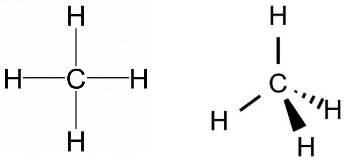
The Lewis structure is misleading because it depicts methane as a planar ‘plus-shaped’ molecule, yet we know that methane is a non-planar, tetrahedral molecule. Representing three dimensions on 2D paper (or computer screen) is challenging. Chemists use dash and wedge notation to draw 3D molecules. Bonds drawn as simple lines are located in the plane of the page or screen. Bonds drawn with a solid triangle, or wedge, represent bonded atoms coming out of the page/screen towards the observer; bonds drawn with dashed triangle, or dash, represent bonded atoms going into the page/screen away from the observer. The correct Lewis structure with dash and wedge notation for CH4 is depicted on the right in Figure 1. It communicates the structure of methane more clearly than a traditional Lewis structure without dash and wedge notation
Notice that on the structure with dash and wedge notation, one carbon-hydrogen bond points straight up from the carbon and is in the plane of the paper (indicated by the simple line). The second carbon-hydrogen bond in the plane of the paper is specifically drawn at ~109° from that first bond. We’ll talk below about why that angle is important to communicate the correct shape of methane. These three atoms define an H-C-H plane that is located in the same plane as the paper/screen. Heading counter-clockwise on the H-C-H plane, the next bond is the solid wedge that represents the carbon-hydrogen bond coming out of the H-C-H plane towards the observer. Notice that it is not pointing straight down, but it is slightly to the right of the center. The fourth carbon-hydrogen bond is going back behind the H-C-H plane away from the observer. Notice that it is not pointing straight to the left, but it is slightly below the horizontal position.
The dash and wedge notation is shown again below (left) adjacent to a space-filling model of CH4 (center) and the ball and stick model (right). All three images represent the same bond placements in space (Figure 2).
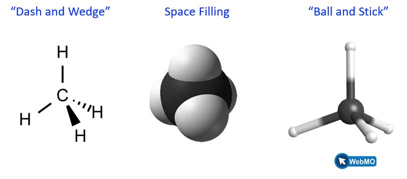
In both the space-filling and ball and stick models, the white spheres represent hydrogen atoms, and the black sphere represents the carbon atom. Training your brain to convert between 2D drawings and 3D bond placement in space is challenging. We recommend manipulating atoms and bonds using both 3D model kits (which can be checked out from College Library) and also online tools. All ball and stick models in this textbook are linked to the WebMO program where you can freely rotate this molecule to better understand the bond positions in 3D space. Once in the program, click on the top, curved arrow (![]() ) on the left-hand toolbar and drag atoms to rotate the molecule.
) on the left-hand toolbar and drag atoms to rotate the molecule.
VSEPR Theory
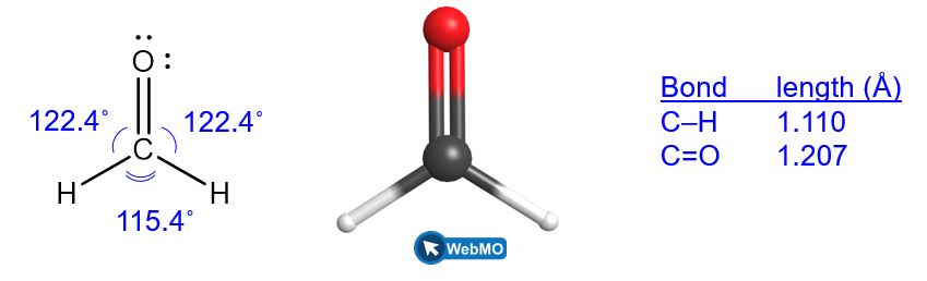
To understand molecular behavior, it is important to be able to describe bonds in terms of their distances, angles, and relative arrangements in space (Figure 3). A bond angle is the angle between any two bonds that include a common atom, usually measured in degrees. A bond distance (or bond length) is the distance between the nuclei of two bonded atoms along the straight line joining the nuclei. Bond distances are typically measured in Ångstroms (1 Å = 10–10 m) or picometers (1 pm = 10–12 m, 100 pm = 1 Å).
Valence shell electron-pair repulsion theory (VSEPR theory) enables us to predict the molecular geometry, including approximate bond angles around a central atom, of a molecule from an examination of the number of bonds and lone electron pairs in its Lewis structure. The VSEPR model assumes that electron pairs in the valence shell of a central atom will adopt an arrangement that minimizes repulsions between these electron pairs by maximizing the distance between them. The electrons in the valence shell of a central atom form either bonding pairs of electrons, located primarily between bonded atoms, or lone pairs. The electrostatic repulsion of these electrons is reduced when the various regions of high electron density assume positions as far from each other as possible.
VSEPR theory predicts the arrangement of electron pairs around each central atom and, usually, the correct arrangement of atoms in a molecule using only electron pair repulsions. This neglects other important factors which contribute to electronic and molecular geometries such as orbital mixing, π conjugation, hyperconjugation, dipole-dipole interactions, hydrogen-bonding, etc. Many of these other factors will be explored in this course and future chemistry courses.
As a simple example of VSEPR theory, let us predict the structure of a gaseous BeF2 molecule. The Lewis structure of BeF2 (Figure 4) shows only two electron pairs around the central beryllium atom. With two bonds and no lone pairs of electrons on the central atom, the bonds are as far apart as possible, and the electrostatic repulsion between these regions of high electron density is reduced to a minimum when they are on opposite sides of the central atom. The F-Be-F bond angle is 180° (Figure 4) in the BeF2 molecule resulting in a linear geometry.

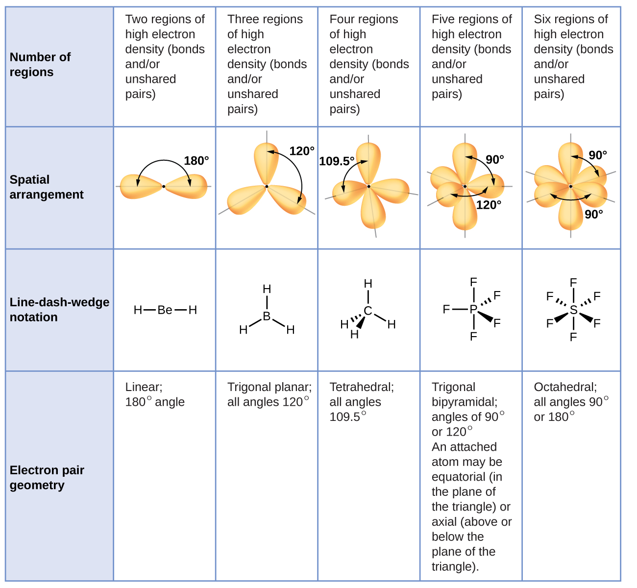
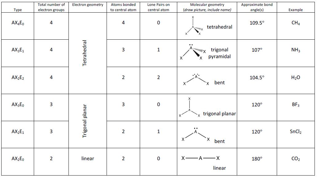
Figure 5 illustrates this and other electron-pair geometries that minimize the repulsions among regions of high electron density (bonds and/or lone pairs). Two regions of electron density around a central atom in a molecule form a linear geometry; three regions form a trigonal planar geometry; four regions form a tetrahedral geometry; five regions form a trigonal bipyramidal geometry; and six regions form an octahedral geometry.
Electron-pair Geometry vs. Molecular Geometry
It is important to note that electron-pair geometry around a central atom is not the same thing as its molecular geometry. The electron-pair geometries shown in Figure 5 describe all regions where electrons are located, bonds as well as lone pairs. Molecular geometry describes the location of the atoms, not the lone pairs. Even though molecular geometry does not describe the location of the lone pairs, the lone pairs still influence the location of the atoms and this influence is still taken into account.
We differentiate between these two situations by naming the geometry that includes all electron pairs the electron-pair geometry. The structure that includes only the placement of the atoms in the molecule is called the molecular geometry. The electron-pair geometries will be the same as the molecular geometry when there are no lone electron pairs around the central atom, but they will be different when there are lone pairs present on the central atom.
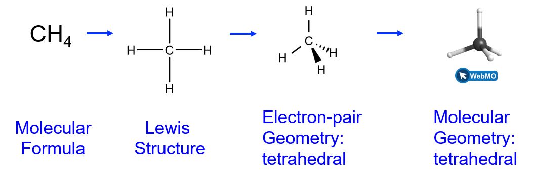
For example, the methane molecule, CH4, which is the major component of natural gas, has four bonding pairs of electrons (i.e., four regions of electron density) around the central carbon atom; the electron-pair geometry is tetrahedral, as is the molecular geometry (Figure 6).
The ammonia molecule, NH3, also has four electron pairs associated with the nitrogen atom (i.e., four regions of electron density), and thus has a tetrahedral electron-pair geometry. One of these regions, however, is a lone pair, which is not included in the molecular geometry, though it does influence the shape of the molecule (Figure 7).
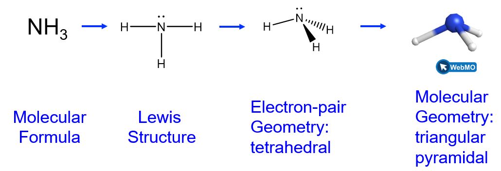
In the ammonia molecule, the three hydrogen atoms attached to the central nitrogen are not arranged in a flat, trigonal planar molecular geometry, but rather in a three-dimensional trigonal pyramid (Figure 7) with the nitrogen atom at the apex and the three hydrogen atoms forming the base. The ideal bond angles in a trigonal pyramid are based on the tetrahedral electron pair geometry. Small bond angle distortions occur due to the lone electron pair on nitrogen. The H–N–H bond angles in NH3 are slightly smaller than the 109.5° angle in a regular tetrahedron.
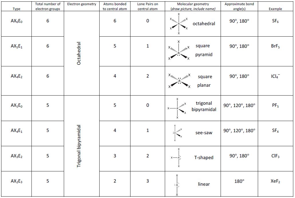
Figure 8 illustrates the ideal molecular geometries, which are predicted based on the electron-pair geometries for various combinations of lone pairs and bonding pairs. Because wedge and dash structures are often confusing at first, we also provide a typical representation of a wedge and dash structure for each combination. While there are other ways that you could rotate the molecule in space and different placements of the wedges and dashes that would also be considered correct, these depictions have been chosen to be the most straightforward to draw and interpret.
Example 1
Predicting Electron-pair Geometry and Molecular Geometry: Lone Pairs on the Central Atom
Predict the electron-pair geometry and molecular geometry of a water molecule.
Solution
The Lewis structure of H2O indicates that there are four regions of high electron density around the oxygen atom: two lone pairs and two chemical bonds:
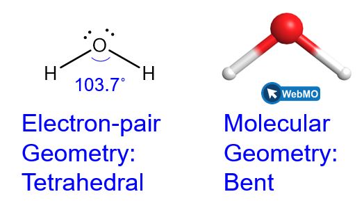
We predict that these four regions are arranged in a tetrahedral (Figure 8) fashion to minimize the electron repulsion, as shown in Figure 9. Thus, the electron-pair geometry is tetrahedral and the molecular geometry is bent with an angle slightly less than 109.5°. In fact, the bond angle is predicted to be 103.7°.
Check Your Learning
The hydronium ion, H3O+, forms when acids are dissolved in water. Predict the electron-pair geometry and molecular geometry of this cation.
Answer:
electron pair geometry: tetrahedral; molecular geometry: trigonal pyramidal
According to VSEPR theory, the terminal atom locations (Xs in Figure 8) are equivalent within the linear, trigonal planar, and tetrahedral electron-pair geometries. It does not matter which X is replaced with a lone pair because the molecules can be rotated to convert positions.
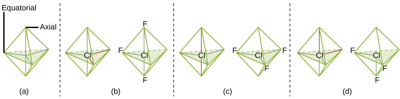
For trigonal bipyramidal electron-pair geometries, however, there are two distinct X positions, as shown in Figure 8: an axial position (if we hold a model of a trigonal bipyramid by the two axial positions, we have an axis around which we can rotate the model) and an equatorial position (three positions form an equator around the middle of the molecule). As shown in Figure 8, the axial position is surrounded by bond angles of 90°, whereas the equatorial position has more space available because of the 120° bond angles. In a trigonal bipyramidal electron-pair geometry, lone pairs or larger atoms or groups tend to occupy equatorial positions rather than axial positions because the equatorial positions are more spacious and minimize electron repulsion.
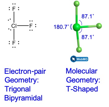
Theoretically, we can come up with three possible arrangements for the three bonds and two lone pairs for the ClF3 molecule (Figure 10). The stable structure is the one that puts the lone pairs in equatorial locations, giving a T-shaped molecular geometry.
When a central atom has two lone electron pairs and four bonding regions, we have an octahedral electron-pair geometry. The two lone pairs are on opposite sides of the octahedron (180° apart), giving a square planar molecular geometry that minimizes lone pair-lone pair repulsions (Figure 8).
Predicting Electron-pair Geometry and Molecular Geometry
The following procedure uses VSEPR theory to determine the electron pair geometries and the molecular geometries:
- Write the Lewis structure of the molecule or polyatomic ion.
- Count the number of regions of electron density (lone pairs and bonds) around the central atom. A single, double, or triple bond counts as one region of electron density.
- Identify the electron-pair geometry based on the number of regions of electron density: linear, trigonal planar, tetrahedral, trigonal bipyramidal, or octahedral (Figure 8).
- Use the number of lone pairs to determine the molecular geometry (Figure 8). If more than one arrangement of lone pairs and chemical bonds is possible, choose the one that will minimize repulsions, remembering that lone pairs occupy more space than multiple bonds, which occupy more space than single bonds. In trigonal bipyramidal arrangements, repulsion is minimized when every lone pair is in an equatorial position. In an octahedral arrangement with two lone pairs, repulsion is minimized when the lone pairs are on opposite sides of the central atom.
The following examples illustrate the use of VSEPR theory to predict the molecular geometry of molecules or ions that have no lone pairs of electrons. In this case, the molecular geometry is identical to the electron pair geometry.
Example 2
Predicting Electron-pair Geometry and Molecular Geometry: CO2 and BH3
Predict the electron-pair geometry and molecular geometry for each of the following:
- carbon dioxide, CO2
- borane, BH3
Solution
(a) We write the Lewis structure of CO2 as:
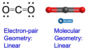
This shows us two regions of high electron density around the carbon atom—each double bond counts as one region, and there are no lone pairs on the carbon atom. Using VSEPR theory, we predict that the two regions of electron density arrange themselves on opposite sides of the central atom with a bond angle of 180°. The electron-pair geometry and molecular geometry are identical, and CO2 molecules are linear.
(b) We write the Lewis structure of BH3 as:
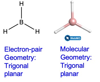
Thus we see that BH3 contains three bonds, and there are no lone pairs of electrons on boron. The arrangement of three regions of high electron density gives a trigonal planar electron-pair geometry. The B–H bonds lie in a plane with 120° angles between them. BH3 also has a trigonal planar molecular geometry.
Check Your Learning
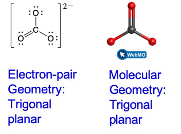
Carbonate, CO32−, is a common polyatomic ion found in various materials from eggshells to antacids. What are the electron-pair geometry and molecular geometry of this polyatomic ion?
Answer:
The electron-pair geometry is trigonal planar and the molecular geometry is trigonal planar. Due to resonance, all three C–O bonds are identical and the bond angles are all 120°. Whether they are single, double, or an average of the two, each bond counts as one region of electron density.
Example 3
Predicting Electron-pair Geometry and Molecular Geometry: Ammonium
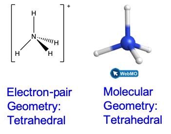
Two of the top 50 chemicals produced in the United States, ammonium nitrate and ammonium sulfate, both used as fertilizers, contain the ammonium ion. Predict the electron-pair geometry and molecular geometry of the NH4+ cation.
Solution
We write the Lewis structure of NH4+ as:

We can see that NH4+ contains four bonds from the nitrogen atom to hydrogen atoms and no lone pairs. We expect the four regions of high electron density to arrange themselves so that they point to the corners of a tetrahedron with the central nitrogen atom in the middle (Figure 8). Therefore, the electron pair geometry of NH4+ is tetrahedral, and the molecular geometry is also tetrahedral.
Check Your Learning
Identify a molecule with trigonal bipyramidal molecular geometry.
Answer:
Any molecule with five electron pairs around the central atoms including no lone pairs will be trigonal bipyramidal. PF5 is a common example.
The next several examples illustrate the effect of lone pairs of electrons on molecular geometry.
Example 4
Predicting Electron-pair Geometry and Molecular Geometry: SF4
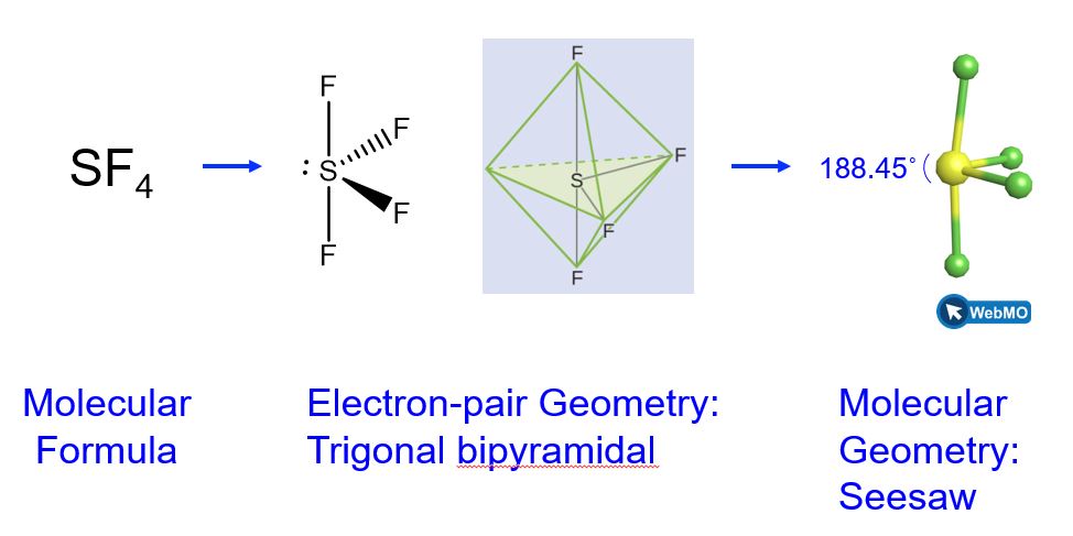
Sulfur tetrafluoride, SF4, is extremely valuable for the preparation of fluorine-containing compounds used as herbicides (i.e., SF4 is used as a fluorinating agent). Predict the electron-pair geometry and molecular geometry of a SF4 molecule.
Solution
The Lewis structure of SF4 indicates five regions of electron density around the sulfur atom: one lone pair and four bonding pairs:
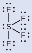
We expect these five regions to adopt a trigonal bipyramidal electron-pair geometry. In the typical fashion, the lone pair occupies one of the equatorial positions, which leads to a trigonal bipyramidal electron-pair geometry and the molecular geometry is that of a seesaw (Figure 8).
Check Your Learning
Predict the electron pair geometry and molecular geometry for molecules of XeF2.
Answer:
The electron-pair geometry is trigonal bipyramidal. The molecular geometry is linear.
Example 5
Predicting Electron-pair Geometry and Molecular Geometry: XeF4
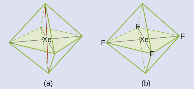
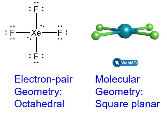
Of all the noble gases, xenon is the most reactive, frequently reacting with elements such as oxygen and fluorine. Predict the electron-pair geometry and molecular geometry of the XeF4 molecule.
Solution
The Lewis structure of XeF4 indicates six regions of high electron density around the xenon atom: two lone pairs and four bonds:
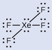
These six regions adopt an octahedral arrangement (Figure 8), which is the electron-pair geometry. To minimize repulsions, the lone pairs should be on opposite sides of the central atom (Figure 15 and Figure 16). The five atoms are all in the same plane and have a square planar molecular geometry.
Check Your Learning
In a certain molecule, the central atom has three lone pairs and two bonds. What will the electron pair geometry and molecular geometry be?
Answer:
electron pair geometry: trigonal bipyramidal; molecular geometry: linear
Molecular Geometry for Multi-center Molecules
When a molecule or polyatomic ion has only one central atom, the molecular geometry completely describes the shape of the molecule. Larger molecules do not have a single central atom, but are connected by a chain of interior atoms that each possess a “local” geometry. The way these local structures are oriented with respect to each other also influences the molecular shape, but such considerations are largely beyond the scope of this introductory discussion. For our purposes, we will only focus on determining the local structures.
Example 6
Predicting Structure in Multicenter Molecules
The Lewis structure for the simplest amino acid, glycine, H2NCH2CO2H, is shown here. Predict the local geometry for the nitrogen atom, the two carbon atoms, and the oxygen atom with a hydrogen atom attached:

Solution

Consider each central atom independently. The electron-pair geometries:
- nitrogen––four regions of electron density, tetrahedral
- carbon (CH2)––four regions of electron density, tetrahedral
- carbon (CO2)—three regions of electron density, trigonal planar
- oxygen (OH)—four regions of electron density, tetrahedral
The local structures:
- nitrogen––three bonds, one lone pair, trigonal pyramidal
- carbon (CH2)—four bonds, no lone pairs, tetrahedral
- carbon (CO2)—three bonds (double bond counts as one region of electron density), no lone pairs, trigonal planar
- oxygen (OH)—two bonds, two lone pairs, bent (109°)
Check Your Learning
Another amino acid is alanine, which has the Lewis structure shown here. Predict the electron-pair geometry and local structure of the nitrogen atom, the three carbon atoms, and the oxygen atom with hydrogen attached:

Answer:
electron-pair geometries:
- nitrogen—tetrahedral
- carbon (CH)—tetrahedral
- carbon (CH3)—tetrahedral
- carbon (CO2)—trigonal planar
- oxygen (OH)—tetrahedral
local structures:
- nitrogen—trigonal pyramidal
- carbon (CH)—tetrahedral
- carbon (CH3)—tetrahedral
- carbon (CO2)—trigonal planar
- oxygen (OH)—bent

The molecular shape simulator lets you build various molecules and practice naming their electron-pair geometries and molecular geometries.
Example 7
Molecular Simulation
Using molecular shape simulator allows us to control whether bond angles and/or lone pairs are displayed by checking or unchecking the boxes under “Options” on the right. We can also use the “Name” checkboxes at bottom-left to display or hide the electron pair geometry (called “electron geometry” in the simulator) and/or molecular geometry (called “molecular shape” in the simulator).
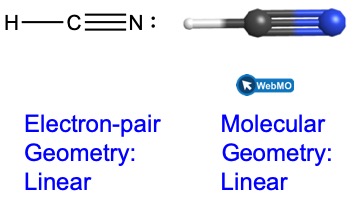
Build the molecule HCN in the simulator based on the following Lewis structure:
Click on each bond type or lone pair at right to add that group to the central atom. Once you have the complete molecule, rotate it to examine the predicted molecular geometry. What molecular geometry is this?
Solution
The molecular geometry is linear.
Check Your Learning
Build a more complex molecule in the simulator. Identify the electron-group geometry, molecular geometry, and bond angles. Then try to find a chemical formula that would match the structure you have drawn.
Answer:
Answers will vary. For example, an atom with four single bonds, a double bond, and a lone pair has an octahedral electron-group geometry and a square pyramidal molecular structure. XeOF4 is a molecule that adopts this structure.
Key Concepts and Summary
VSEPR theory predicts the three-dimensional arrangement of atoms in a molecule. It states that valence electrons will assume an electron-pair geometry that minimizes repulsions between areas of high electron density (bonds and/or lone pairs). Molecular geometry, which refers only to the placement of atoms in a molecule and not the electrons, is equivalent to electron-pair geometry only when there are no lone electron pairs around the central atom. When lone electron pairs exist, they affect the molecular geometry, even if their location is not directly specified in the molecular geometry name.
Being able to convert between 2D and 3D representations of molecules in your head is important and takes practice. Remember to use the resources mentioned in this section to practice manipulating these structures.
Glossary
- axial position
- location in a trigonal bipyramidal geometry in which there is another atom at a 180° angle and the equatorial positions are at a 90° angle
- bond angle
- angle between any two covalent bonds that share a common atom
- bond distance
- (also, bond length) distance between the nuclei of two bonded atoms
- electron-pair geometry
- arrangement around a central atom of all regions of electron density (bonds, lone pairs, or unpaired electrons)
- equatorial position
- one of the three positions in a trigonal bipyramidal geometry with 120° angles between them; the axial positions are located at a 90° angle
- linear
- shape in which two outside groups are placed on opposite sides of a central atom
- molecular geometry
- structure that includes only the placement of the atoms in the molecule
- octahedral
- shape in which six outside groups are placed around a central atom such that a three-dimensional shape is generated with four groups forming a square and the other two forming the apex of two pyramids, one above and one below the square plane
- tetrahedral
- shape in which four outside groups are placed around a central atom such that a three-dimensional shape is generated with four corners and 109.5° angles between each pair and the central atom
- trigonal bipyramidal
- shape in which five outside groups are placed around a central atom such that three form a flat triangle with 120° angles between each pair and the central atom, and the other two form the apex of two pyramids, one above and one below the triangular plane
- trigonal planar
- shape in which three outside groups are placed in a flat triangle around a central atom with 120° angles between each pair and the central atom
- valence shell electron-pair repulsion theory (VSEPR)
- theory used to predict the bond angles in a molecule based on positioning regions of high electron density as far apart as possible to minimize electrostatic repulsion
Chemistry End of Section Exercises
- Explain why the HOH molecule is bent, whereas the HBeH molecule is linear.
- What feature of a Lewis structure can be used to tell if a molecule’s (or ion’s) electron-pair geometry and molecular geometry will be identical?
- Explain the difference between electron-pair geometry and molecular geometry.
- Predict the electron pair geometry and the molecular geometry of each of the following molecules or ions:
- SF6
- PCl5
- BeH2
- CH3+
- What are the electron-pair geometry and the molecular geometry of each of the following molecules or ions?
- ClF5
- ClO2−
- TeCl42−
- PCl3
- SeF4
- PH2−
- Identify the electron pair geometry and the molecular geometry of each of the following molecules:
- ClNO (N is the central atom)
- CS2
- Cl2CO (C is the central atom)
- Cl2SO (S is the central atom)
- SO2F2 (S is the central atom)
- XeO2F2 (Xe is the central atom)
- ClOF2+ (Cl is the central atom)
- Describe the molecular geometry around the indicated atom or atoms:
- the sulfur atom in sulfuric acid, H2SO4 [(HO)2SO2]
- the chlorine atom in chloric acid, HClO3 [HOClO2]
- the oxygen atom in hydrogen peroxide, HOOH
- the nitrogen atom in nitric acid, HNO3 [HONO2]
- the oxygen atom in the OH group in nitric acid, HNO3 [HONO2]
- the central oxygen atom in the ozone molecule, O3
- each of the carbon atoms in propyne, CH3CCH
- the carbon atom in Freon, CCl2F2
- each of the carbon atoms in allene, H2CCCH2
- Draw the Lewis electron dot structures for these molecules, including resonance structures where appropriate:
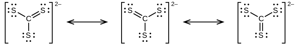
- CS32−
- CS2
- CS
- predict the molecular shapes for CS32− and CS2 and explain how you arrived at your predictions
- What is the molecular geometry of the stable form of FNO2? (N is the central atom.)
- Use VSEPR theory to predict the electron-pair geometry and the molecular geometry of the chlorate ion, ClO3–.
Answers to Chemistry End of Section Exercises
- The placement of the two sets of unpaired electrons in water forces the bonds to assume a tetrahedral arrangement, and the resulting HOH molecule is bent. The HBeH molecule (in which Be has only two electrons to bond with the two electrons from the hydrogens) must have the electron pairs as far from one another as possible and is therefore linear.
- Absence of electron pairs on the central atom.
- Space must be provided for each pair of electrons whether they are in a bond or are present as lone pairs. Electron-pair geometry considers the placement of all electrons. Molecular geometry considers only the bonding-pair geometry.
- (a) Both the electron geometry and the molecular geometry are octahedral.
(b) Both the electron geometry and the molecular geometry are trigonal bipyramid.
(c) Both the electron geometry and the molecular geometry are linear.
(d) Both the electron geometry and the molecular geometry are trigonal planar. - (a) electron-pair geometry: octahedral, molecular geometry: square pyramidal
(b) electron-pair geometry: tetrahedral, molecular geometry: bent
(c) electron-pair geometry: octahedral, molecular geometry: square planar
(d) electron-pair geometry: tetrahedral, molecular geometry: trigonal pyramidal
(e) electron-pair geometry: trigonal bypyramidal, molecular geometry: seesaw
(f) electron-pair geometry: tetrahedral, molecular geometry: bent - (a) electron-pair geometry: trigonal planar, molecular geometry: bent
(b) electron-pair geometry: linear, molecular geometry: linear
(c) electron-pair geometry: trigonal planar, molecular geometry: trigonal planar
(d) electron-pair geometry: tetrahedral, molecular geometry: trigonal pyramidal
(e) electron-pair geometry: tetrahedral, molecular geometry: tetrahedral
(f) electron-pair geometry: trigonal bipyramidal, molecular geometry: seesaw
(g) electron-pair geometry: tetrahedral, molecular geometry: trigonal pyramidal - (a) tetrahedral; (b) trigonal pyramidal; (c) bent; (d) trigonal planar; (e) bent; (f) bent
(g) CH3CCH tetrahedral, CH3CCH linear; (h) tetrahedral
(i) H2CCCH2 linear; H2CCCH2 trigonal planar - (a)
(b)
(c)
(d) CS32− includes three regions of electron density (all are bonds with no lone pairs); the shape is trigonal planar; CS2 has only two regions of electron density (all bonds with no lone pairs); the shape is linear - trigonal planar
- electron-pair geometry: tetrahedral, molecular geometry: trigonal pyramidal
Please use this form to report any inconsistencies, errors, or other things you would like to change about this page. We appreciate your comments. 🙂
