
M11Q6: Ionic Crystals and Unit Cell Stoichiometry
Introduction
Now that we have have explored unit cells, we will look at ionic crystals. By examining the ratio of cations to anions in an ionic crystal, we can determine the stoichiometry of an ionic compound.
Learning Objectives for Ionic Crystals and Unit Cell Stoichiometry
- Calculate unit cell stoichiometry, given a depiction of the unit cell.
| Structures of Ionic Crystals | Unit Cells of Ionic Compounds | X-ray Crystallography |
| Key Concepts and Summary | Key Equations | Glossary | End of Section Exercises |
Structures of Ionic Crystals
Ionic crystals consist of two or more different kinds of ions that usually have different sizes. The packing of these ions into a crystal structure is more complex than the packing of metal atoms that are the same size.
Most monatomic ions behave as charged spheres, and their attraction for ions of opposite charge is the same in every direction. Consequently, stable structures for ionic compounds result (1) when ions of one charge are surrounded by as many ions as possible of the opposite charge and (2) when the cations and anions are in contact with each other. Structures are determined by two principal factors: the relative sizes of the ions and the ratio of the numbers of positive and negative ions in the compound.
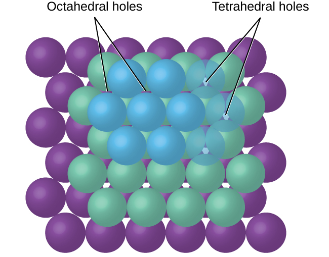
In simple ionic structures, we usually find the anions, which are normally larger than the cations, arranged in a closest-packed array. (As seen previously, additional electrons attracted to the same nucleus make anions larger and fewer electrons attracted to the same nucleus make cations smaller when compared to the atoms from which they are formed.) The smaller cations commonly occupy one of two types of holes (or interstices) remaining between the anions. The smaller of the holes is found between three anions in one plane and one anion in an adjacent plane. The four anions surrounding this hole are arranged at the corners of a tetrahedron, so the hole is called a tetrahedral hole. The larger type of hole is found at the center of six anions (three in one layer and three in an adjacent layer) located at the corners of an octahedron; this is called an octahedral hole. Figure 1 illustrates both of these types of holes.
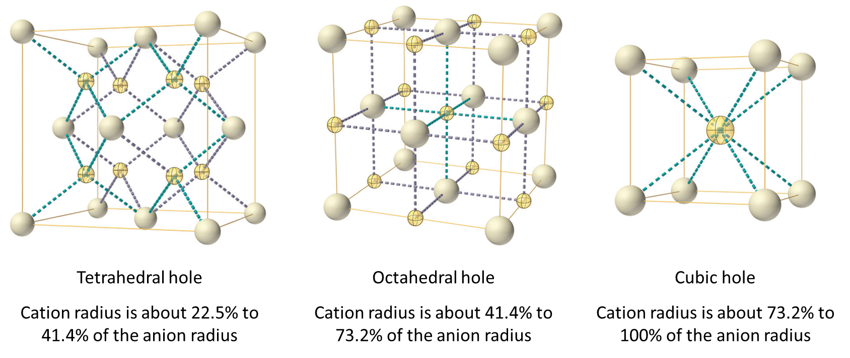
Depending on the relative sizes of the cations and anions, the cations of an ionic compound may occupy tetrahedral or octahedral holes, as illustrated in Figure 2. Relatively small cations occupy tetrahedral holes, and larger cations occupy octahedral holes. If the cations are too large to fit into the octahedral holes, the anions may adopt a more open structure, such as a simple cubic array. The larger cations can then occupy the larger cubic holes made possible by the more open spacing.
There are two tetrahedral holes for each anion in a CCP array of anions. A compound that crystallizes in a closest-packed array of anions with cations in the tetrahedral holes can have a maximum cation:anion ratio of 2:1; all of the tetrahedral holes are filled at this ratio. Examples include Li2O, Na2O, Li2S, and Na2S. Compounds with a ratio of less than 2:1 may also crystallize in a closest-packed array of anions with cations in the tetrahedral holes, if the ionic sizes fit. In these compounds, however, some of the tetrahedral holes remain vacant.
Example 1
Occupancy of Tetrahedral Holes
Zinc sulfide is an important industrial source of zinc and is also used as a white pigment in paint. Zinc sulfide crystallizes with zinc ions occupying one-half of the tetrahedral holes in a closest-packed array of sulfide ions. What is the formula of zinc sulfide?
Solution
Because there are two tetrahedral holes per anion (sulfide ion) and one-half of these holes are occupied by zinc ions, there must be ½ × 2, or 1, zinc ion per sulfide ion. Thus, the formula is ZnS.
Check Your Learning
Lithium selenide can be described as a closest-packed array of selenide ions with lithium ions in all of the tetrahedral holes. What it the formula of lithium selenide?
Answer:
Li2Se
The ratio of octahedral holes to anions in a CCP structure is 1:1. Thus, compounds with cations in octahedral holes in a closest-packed array of anions can have a maximum cation:anion ratio of 1:1. In NiO, MnS, NaCl, and KH, for example, all of the octahedral holes are filled. Ratios of less than 1:1 are observed when some of the octahedral holes remain empty.
Example 2
Stoichiometry of Ionic Compounds
Sapphire is aluminum oxide. Aluminum oxide crystallizes with aluminum ions in two-thirds of the octahedral holes in a closest-packed array of oxide ions. What is the formula of aluminum oxide?
Solution
Because there is one octahedral hole per anion (oxide ion) and only two-thirds of these holes are occupied, the ratio of aluminum to oxygen must be  :1, which would give Al2/3O. The simplest whole number ratio is 2:3, so the formula is Al2O3.
Check Your Learning
The white pigment titanium oxide crystallizes with titanium ions in one-half of the octahedral holes in a closest-packed array of oxide ions. What is the formula of titanium oxide?
Answer:
TiO2
In a primitive cubic array of anions, there is one cubic hole that can be occupied by a cation for each anion in the array. In CsCl, and in other compounds with the same structure, all of the cubic holes are occupied. Half of the cubic holes are occupied in SrH2, UO2, SrCl2, and CaF2.
Different types of ionic compounds often crystallize in the same structure when the relative sizes of their ions and their stoichiometries (the two principal features that determine structure) are similar.
Unit Cells of Ionic Compounds
Many ionic compounds crystallize with cubic unit cells, and we will use these compounds to describe the general features of ionic structures.
When an ionic compound is composed of cations and anions of similar size in a 1:1 ratio, it typically forms a primitive cubic structure. Cesium chloride, CsCl, (illustrated in Figure 3) is an example of this, with Cs+ and Cl− having radii of 174 pm and 181 pm, respectively. We can think of this as chloride ions forming a primitive cubic unit cell, with a cesium ion in the center; or as cesium ions forming a unit cell with a chloride ion in the center; or as primitive cubic unit cells formed by Cs+ ions overlapping unit cells formed by Cl− ions. Cesium ions and chloride ions touch along the body diagonals of the unit cells. One cesium ion and one chloride ion are present per unit cell, giving the l:l stoichiometry required by the formula for cesium chloride. Note that there is no lattice point in the center of the cell, and CsCl is not a BCC structure because a cesium ion is not identical to a chloride ion.
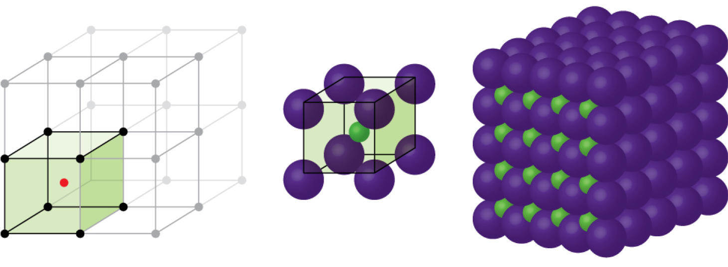
We have said that the location of lattice points is arbitrary. This is illustrated by an alternate description of the CsCl structure in which the lattice points are located in the centers of the cesium ions. In this description, the cesium ions are located on the lattice points at the corners of the cell, and the chloride ion is located at the center of the cell. The two unit cells are different, but they describe identical structures.
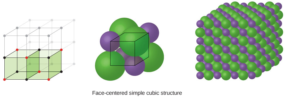
When an ionic compound is composed of a 1:1 ratio of cations and anions that differ significantly in size, it typically crystallizes with an FCC unit cell, like that shown in Figure 4. Sodium chloride, NaCl, is an example of this, with Na+ and Cl− having radii of 102 pm and 181 pm, respectively. We can think of this as chloride ions forming an FCC cell, with sodium ions located in the octahedral holes in the middle of the cell edges and in the center of the cell. The sodium and chloride ions touch each other along the cell edges. The unit cell contains four sodium ions and four chloride ions, giving the 1:1 stoichiometry required by the formula, NaCl.
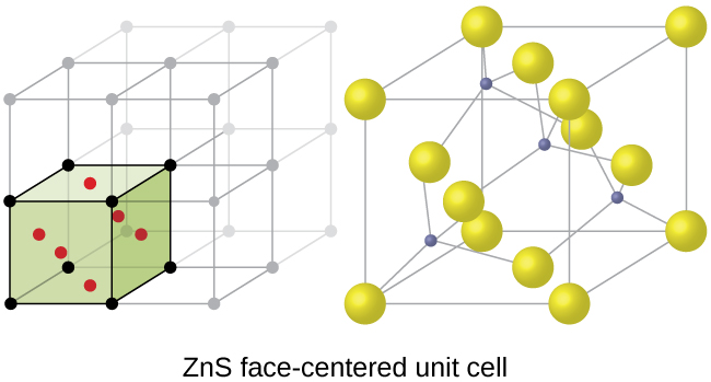
The cubic form of zinc sulfide, zinc blende, also crystallizes in an FCC unit cell, as illustrated in Figure 5. This structure contains sulfide ions on the lattice points of an FCC lattice. (The arrangement of sulfide ions is identical to the arrangement of chloride ions in sodium chloride.) The radius of a zinc ion is only about 40% of the radius of a sulfide ion, so these small Zn2+ ions are located in alternating tetrahedral holes, that is, in one half of the tetrahedral holes. There are four zinc ions and four sulfide ions in the unit cell, giving the empirical formula ZnS.
Calculation of Ionic Radii
If we know the edge length of a unit cell of an ionic compound and the position of the ions in the cell, we can calculate ionic radii for the ions in the compound if we make assumptions about individual ionic shapes and contacts.
Example 3
Calculation of Ionic Radii
The edge length of the unit cell of LiCl (NaCl-like structure, FCC) is 0.514 nm or 5.14 Å. Assuming that the lithium ion is small enough so that the chloride ions are in contact, as in Figure 4, calculate the ionic radius for the chloride ion.
Note: The length unit angstrom, Å, is often used to represent atomic-scale dimensions and is equivalent to 10−10 m.
Solution
On the face of a LiCl unit cell, chloride ions contact each other across the diagonal of the face:
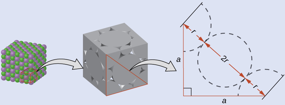
Drawing a right triangle on the face of the unit cell, we see that the length of the diagonal is equal to four chloride radii (one radius from each corner chloride and one diameter—which equals two radii—from the chloride ion in the center of the face), so d = 4r. From the Pythagorean theorem, we have:
a2 + a2 = d2
which yields:
(0.514 nm)2 + (0.514 nm)2 = (4r)2 = 16r2
Solving this gives a Cl– radius of:
r =  = 0.182 nm (1.82 Å)
Check Your Learning
The edge length of the unit cell of KCl (NaCl-like structure, FCC) is 6.28 Å. Assuming anion-cation contact along the cell edge, calculate the radius of the potassium ion. The radius of the chloride ion is 1.82 Å.
Answer:
The radius of the potassium ion is 1.33 Å.
It is important to realize that values for ionic radii calculated from the edge lengths of unit cells depend on numerous assumptions, such as a perfect spherical shape for ions, which are approximations at best. Hence, such calculated values are themselves approximate and comparisons cannot be pushed too far. Nevertheless, this method has proved useful for calculating ionic radii from experimental measurements such as X-ray crystallographic determinations.
X-Ray Crystallography
The size of the unit cell and the arrangement of atoms in a crystal may be determined from measurements of the diffraction of X-rays by the crystal, termed X-ray crystallography. Diffraction is the change in the direction of travel experienced by an electromagnetic wave when it encounters a physical barrier whose dimensions are comparable to those of the wavelength of the light. X-rays are electromagnetic radiation with wavelengths about as long as the distance between neighboring atoms in crystals (on the order of a few Å).
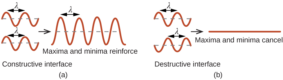
When a beam of monochromatic X-rays strikes a crystal, its rays are scattered in all directions by the atoms within the crystal. When scattered waves traveling in the same direction encounter one another, they undergo interference, a process by which the waves combine to yield either an increase or a decrease in amplitude (intensity) depending upon the extent to which the combining waves’ maxima are separated (see Figure 6).
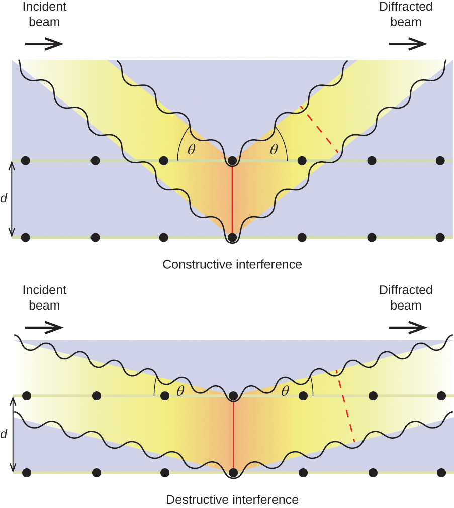
When X-rays of a certain wavelength, λ, are scattered by atoms in adjacent crystal planes separated by a distance, d, they may undergo constructive interference when the difference between the distances traveled by the two waves prior to their combination is an integer factor, n, of the wavelength. This condition is satisfied when the angle of the diffracted beam, θ, is related to the wavelength and interatomic distance by the equation:
nλ = 2d sin(θ)
This relation is known as the Bragg equation in honor of W. H. Bragg, the English physicist who first explained this phenomenon. Figure 7 illustrates two examples of diffracted waves from the same two crystal planes. The figure on the top depicts waves diffracted at the Bragg angle, resulting in constructive interference, while that on the bottom shows diffraction and a different angle that does not satisfy the Bragg condition, resulting in destructive interference.

Visit this site for more details on the Bragg equation and a simulator that allows you to explore the effect of each variable on the intensity of the diffracted wave.
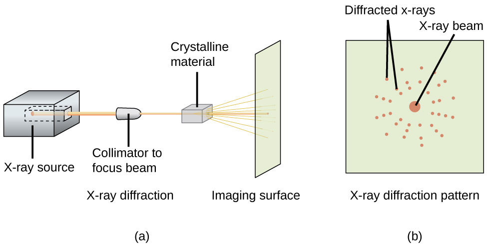
An X-ray diffractometer, such as the one illustrated in Figure 8, may be used to measure the angles at which X-rays are diffracted when interacting with a crystal as described earlier. From such measurements, the Bragg equation may be used to compute distances between atoms.
Chemistry in Real Life: X-ray Crystallographer Rosalind Franklin
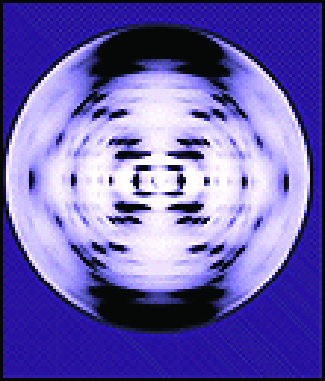
The discovery of the structure of DNA in 1953 by Francis Crick and James Watson is one of the great achievements in the history of science. They were awarded the 1962 Nobel Prize in Physiology or Medicine, along with Maurice Wilkins, who provided experimental proof of DNA’s structure. British chemist Rosalind Franklin made invaluable contributions to this monumental achievement through her work in measuring X-ray diffraction images of DNA. Early in her career, Franklin’s research on the structure of coals proved helpful to the British war effort. After shifting her focus to biological systems in the early 1950s, Franklin and doctoral student Raymond Gosling discovered that DNA consists of two forms: a long, thin fiber formed when wet (type “B”) and a short, wide fiber formed when dried (type “A”). Her X-ray diffraction images of DNA (Figure 9) provided the crucial information that allowed Watson and Crick to confirm that DNA forms a double helix, and to determine details of its size and structure. Franklin also conducted pioneering research on viruses and the RNA that contains their genetic information, uncovering new information that radically changed the body of knowledge in the field. After developing ovarian cancer, Franklin continued to work until her death in 1958 at age 37. Among many posthumous recognitions of her work, the Chicago Medical School of Finch University of Health Sciences changed its name to the Rosalind Franklin University of Medicine and Science in 2004, and adopted an image of her famous X-ray diffraction image of DNA as its official university logo.
Key Concepts and Summary
The anions in simple ionic structures commonly adopt a cubic unit cell, and the cations occupy the spaces remaining between the anions. Small cations usually occupy tetrahedral holes in a closest-packed array of anions. Larger cations usually occupy octahedral holes. Still larger cations can occupy cubic holes in a simple cubic array of anions. The structure of a solid can be described by indicating the size and shape of a unit cell and the contents of the cell. The type of structure and dimensions of the unit cell can be determined by X-ray diffraction measurements.
Key Equations
- nλ = 2d sin(θ)
Glossary
- Bragg equation
- equation that relates the angles at which X-rays are diffracted by the atoms within a crystal
- diffraction
- redirection of electromagnetic radiation that occurs when it encounters a physical barrier of appropriate dimensions
- hole
- (also, interstice) space between atoms within a crystal
- octahedral hole
- open space in a crystal at the center of six particles located at the corners of an octahedron
- space lattice
- all points within a crystal that have identical environments
- tetrahedral hole
- tetrahedral space formed by four atoms or ions in a crystal
- X-ray crystallography
- experimental technique for determining distances between atoms in a crystal by measuring the angles at which X-rays are diffracted when passing through the crystal
Chemistry End of Section Exercises
- Cadmium sulfide, sometimes used as a yellow pigment by artists, crystallizes with cadmium, occupying one-half of the tetrahedral holes in a closest packed array of sulfide ions. What is the formula of cadmium sulfide? Explain your answer.
- A compound of cadmium, tin, and phosphorus is used in the fabrication of some semiconductors. It crystallizes with cadmium occupying one-fourth of the tetrahedral holes and tin occupying one-fourth of the tetrahedral holes in a closest packed array of phosphide ions. What is the formula of the compound? Explain your answer.
- What is the formula of the magnetic oxide of cobalt, used in recording tapes, that crystallizes with cobalt atoms occupying one-eighth of the tetrahedral holes and one-half of the octahedral holes in a closely packed array of oxide ions?
- A compound containing zinc, aluminum, and sulfur crystallizes with a closest-packed array of sulfide ions. Zinc ions are found in one-eighth of the tetrahedral holes and aluminum ions in one-half of the octahedral holes. What is the empirical formula of the compound?
- A compound of thallium and iodine crystallizes in a simple cubic array of iodide ions with thallium ions in all of the cubic holes. What is the formula of this iodide? Explain your answer.
- Which of the following elements reacts with sulfur to form a solid in which the sulfur atoms form a closest-packed array with all of the octahedral holes occupied: Li, Na, Be, Ca, or Al?
- What is the percent by mass of titanium in rutile, a mineral that contains titanium and oxygen, if structure can be described as a closest packed array of oxide ions with titanium ions in one-half of the octahedral holes? What is the oxidation number of titanium?
- Rubidium iodide crystallizes with a cubic unit cell that contains iodide ions at the corners and a rubidium ion in the center. What is the formula of the compound?
- One of the various manganese oxides crystallizes with a cubic unit cell that contains manganese ions at the corners and in the center. Oxide ions are located at the center of each edge of the unit cell. What is the formula of the compound?
Answers to Chemistry End of Section Exercises
- In a closest-packed array, two tetrahedral holes exist for each anion. If only half the tetrahedral holes are occupied, the numbers of anions and cations are equal. The formula for cadmium sulfide is CdS.
- CdSnP2; since Cd and Sn take up ¼ of the holes each, then per P, there are ½ Cd and ½ Sn. The smallest whole number ratio would be a 1:1:2 ratio
- Co3O4
- ZnAl2S4
- In a simple cubic array, only one cubic hole can be occupied be a cation for each anion in the array. The ratio of thallium to iodide must be 1:1; therefore, the formula for thallium is TlI.
- Ca
- 59.95%; The oxidation number of titanium is +4.
- RbI
- Mn2O3
Please use this form to report any inconsistencies, errors, or other things you would like to change about this page. We appreciate your comments. 🙂
