
M7Q4: Wave Interference, Diffraction
Introduction
As the quest continued to resolve scientific paradoxes in classical physics, scientists needed to completely revise the way they thought about matter. This section examines the behavior of interference and diffraction of waves.
Learning Objectives for Wave Interference, Diffraction
- Illustrate how the diffraction of electrons reveals the wave properties of matter.
| Wave Interference and Diffraction | Light Behaves as a Wave |
Wave Interference and Diffraction
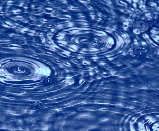
If you were to drop a stone into a still pond, you would see waves ripple outward from the center of a circle. If you were to drop multiple stones into a still pond, you would see these same waves ripple outward, but when the waves meet, the pattern would change. When two or more waves come into contact, they interfere with each other. Interacting waves on the surface of water can produce interference patterns similar to those shown below (Figure 1).
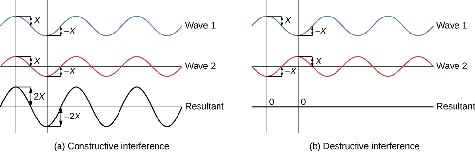
There are two types of wave interference. Constructive interference occurs in regions where the peaks or troughs for the two waves coincide (Figure 2a). Destructive interference occurs in regions where the peak of one wave coincides with the trough of another wave (Figure 2b). The amplitudes of the interfering waves add together and produce a resultant wave, as shown below.
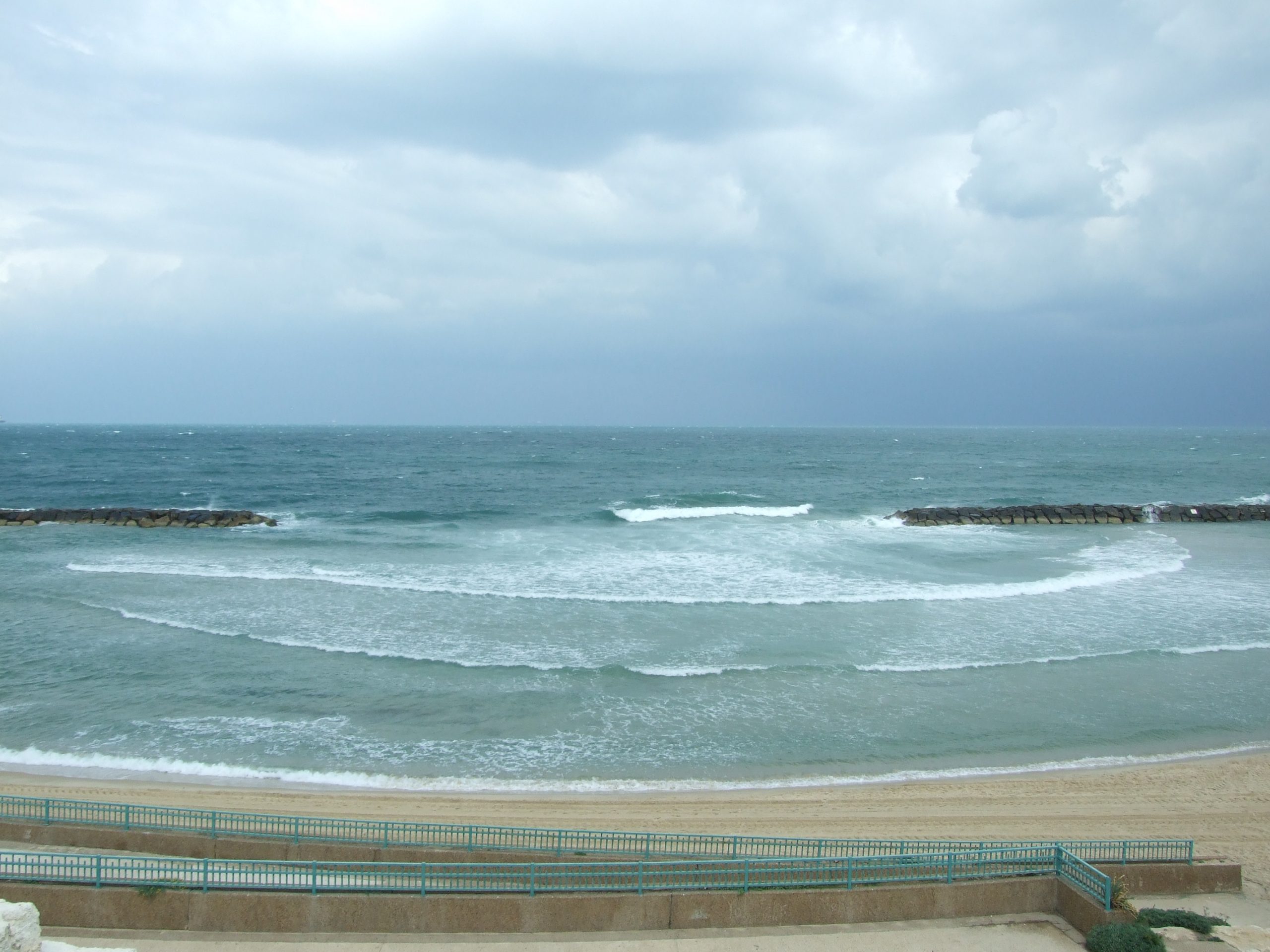
Diffraction of waves occurs when a wave encounters an obstacle—the wave appears to bend around a small obstacle or spread out in semicircles after an opening. Consider the water waves in Figure 3 that show how water waves diffract and form large semicircles after passing through a breakwater.
Light Behaves as a Wave
The interference that is seen in water waves is also seen with light, which indicates that light behaves like a wave. Figure 4 shows the interference patterns that arise when light passes through narrow slits closely spaced about a wavelength apart. If light behaved as a classic particle, shining a light through two narrowly spaced slits would result in just two lines on the screen (one for the light particles passing through each slit). The fact that an interference pattern occurs indicates that a pure particle definition of light is not accurate. The fringe patterns produced depend on the wavelength. If you were to pass short and long wavelength light through a set of slits, the shorter wavelength light will produce more closely spaced fringes than longer wavelength light. When the light passes through the two slits, each slit effectively acts as a new source, resulting in two closely spaced waves coming into contact at the detector (the camera in this case). The dark regions in Figure 4 correspond to regions where the peaks for the wave from one slit happen to coincide with the troughs for the wave from the other slit (destructive interference), while the brightest regions correspond to the regions where the peaks for the two waves (or their two troughs) happen to coincide (constructive interference). Such interference patterns cannot be explained by particles moving according to the laws of classical mechanics.

If light passes through a slit, it will also produce a similar wave pattern as depicted in Figure 3. A wave passing through two small openings spaced closely together will spread out and begin to interfere, as seen in Figure 5. A wave comes from the left and is incident on two slits, which diffract the plane wave. The interference pattern produced when light diffracts cannot be explained by particles moving according to the laws of classical mechanics and will be discussed in greater detail in the following section.
Since the photoelectric effect showed that light has particle-like characteristics, and light diffraction and interferences shows that light has wave-like properties, we often refer to the wave-particle duality of light: Light has both wave-like and particle-like properties.
Key Concepts and Summary
Waves exhibit diffraction and interference. Electromagnetic radiation that passes through two closely spaced narrow slits having dimensions roughly similar to the wavelength will show an interference pattern that is a result of constructive and destructive interference of the waves. Since light is diffracted when passing through narrow slits, and since light can produce interference patterns, we say that light behaves as a wave. These processes cannot be explained by particles moving according to classical mechanics.
Glossary
- constructive interference
- when the peaks or troughs for two waves coincide to produce a wave that is the sum of the two individual waves
- destructive interference
- when the peak of one wave coincides with trough of another wave to either cancel the wave entirely or produce a smaller wave
- diffraction
- the process by which a beam of light is spread out upon encountering an obstacle in its path, typically accompanied by interference between the wave forms produced
Chemistry End of Section Exercises
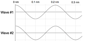
- True or False: The following waves would interfere constructively.
Answers to Chemistry End of Section Exercises
- True
Please use this form to report any inconsistencies, errors, or other things you would like to change about this page. We appreciate your comments. 🙂
