M18Q7: Batteries and Fuel Cells

Learning Objectives

| Key Concepts and Summary | Glossary | End of Section Exercises |

A battery is an electrochemical cell or series of cells that produces an electric current. In principle, any galvanic cell could be used as a battery. An ideal battery would never run down, produce an unchanging voltage, and be capable of withstanding environmental extremes of heat and humidity. Real batteries strike a balance between ideal characteristics and practical limitations. For example, the mass of a car battery is about 18 kg or about 1% of the mass of an average car or light-duty truck. This type of battery would supply nearly unlimited energy if used in a smartphone, but would be rejected for this application because of its mass. Thus, no single battery is “best” and batteries are selected for a particular application, keeping things like the mass of the battery, its cost, reliability, and current capacity in mind. There are two basic types of batteries: primary and secondary. A few batteries of each type are described next.

Primary Batteries

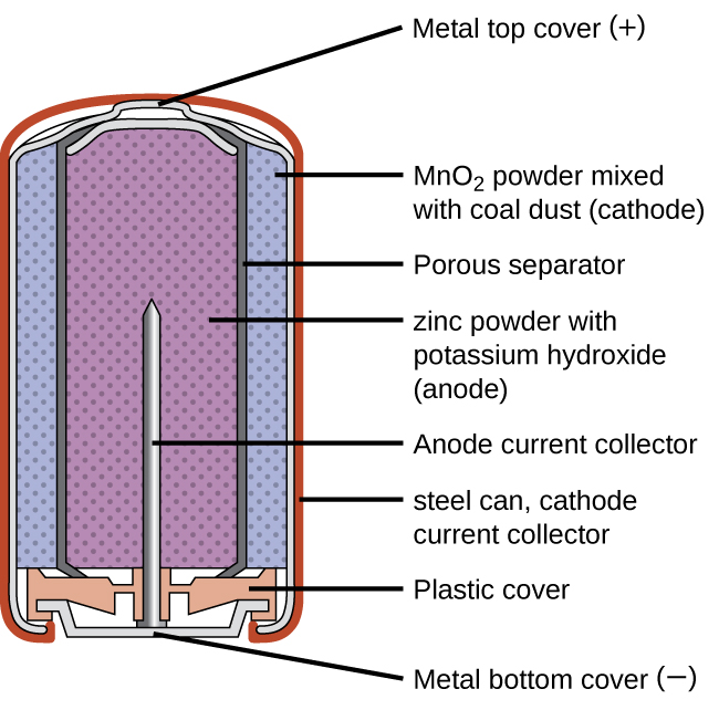
Primary batteries are single-use batteries because they cannot be recharged. A common primary battery type is an alkaline battery (Figure 1) developed in the 1950s. As their name suggests, these types of batteries use alkaline electrolytes, often potassium hydroxide. The reactions are:

Anode: Zn(s) + 2 OH(aq) ZnO(s) + H2O(ℓ) + 2 e
Cathode: 2 MnO2(s) + H2O(ℓ) + 2 e Mn2O3(s) + 2 OH(aq)
Overall: Zn(s) + 2 MnO2(s) ZnO(s) + Mn2O3(s)

While some alkaline batteries are rechargeable, most are not. Attempts to recharge an alkaline battery that is not rechargeable often leads to rupture of the battery and leakage of the potassium hydroxide electrolyte.

A diagram of a cross section of an alkaline battery is shown. The overall shape of the cell is cylindrical. The lateral surface of the cylinder, indicated as a thin red line, is labeled “Outer casing.” Just beneath this is a thin, light grey surface that covers the lateral surface and top of the battery. Inside is a blue region with many evenly spaced small darker dots, labeled “M n O subscript 2 (cathode).” A thin dark grey layer is just inside, which is labeled “Ion conducting separator.” A purple region with many evenly spaced small darker dots fills the center of the battery and is labeled “ zinc (anode).” The very top of the battery has a thin grey curved surface over the central purple region. The curved surface above is labeled “Positive connection (plus).” At the base of the battery, an orange structure, labeled “Protective cap,” is located beneath the purple and blue central regions. This structure holds a grey structure that looks like a nail with its head at the bottom and pointed end extending upward into the center of the battery. This nail-like structure is labeled “Current pick up.” At the very bottom of the battery is a thin grey surface that is held by the protective cap. This surface is labeled “Negative terminal (negative).”
Figure 1. Alkaline batteries were designed as direct replacements for zinc-carbon (dry cell) batteries.

Secondary Batteries

Secondary batteries are rechargeable. These are the types of batteries found in devices such as smartphones, electronic tablets, and automobiles.

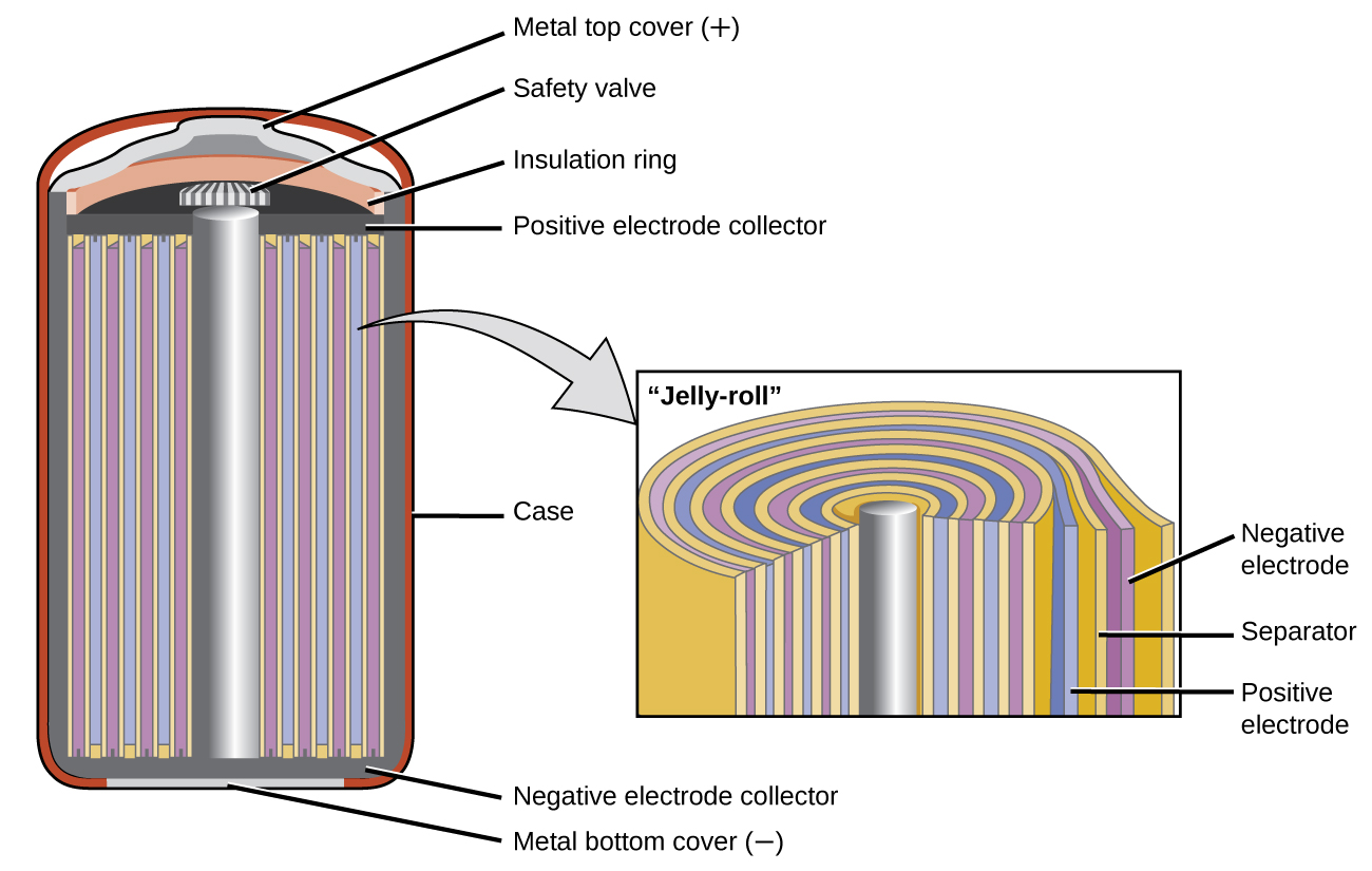
Nickel-cadmium, or NiCd, batteries (Figure 2) consist of a nickel-plated cathode, cadmium-plated anode, and a potassium hydroxide electrode. The positive and negative plates, which are prevented from direct connection by the separator, are rolled together and put into the case. This is a “jelly-roll” design and allows the NiCd cell to deliver much more current than a similar-sized alkaline battery. The reactions are:

Anode: Cd(s) + 2 OH(aq) Cd(OH)2(s) + 2 e
Cathode: NiO2(s) + 2 H2O(ℓ) + 2 e Ni(OH)2(s) + 2 OH(aq)
Overall: Cd(s) + NiO2(s) + 2 H2O(ℓ) Cd(OH)2(s) + Ni(OH)2(s)

The voltage is about 1.2 V to 1.25 V as the battery discharges. When properly treated, a NiCd battery can be recharged about 1000 times. Cadmium is a toxic heavy metal so NiCd batteries should never be opened or put into the regular trash.

A diagram is shown of a cross section of a nickel cadmium battery. This battery is in a cylindrical shape. An outer red layer is labeled “case.” Just inside this layer is a thin, dark grey layer which is labeled at the bottom of the cylinder as “Negative electrode collector.” A silver rod extends upward through the center of the battery, which is surrounded by alternating layers, shown as vertical repeating bands, of yellow, purple, yellow, and blue. A slightly darker grey narrow band extends across the top of these alternating bands, which is labeled “Positive electrode collector.” A thin light grey band appears at the very bottom of the cylinder, which is labeled “Metal bottom cover (negative).” A small grey and white striped rectangular structure is present at the top of the central silver cylinder, which is labeled “Safety valve.” Above this is an orange layer that curves upward over the safety valve, which is labeled “Insulation ring.” Above this is a thin light grey layer that projects upward slightly at the center, which is labeled “Metal top cover (plus).” A light grey arrow points to a rectangle to the right that illustrates the layers at the center of the battery under magnification. From the central silver rod, the layers shown repeat the alternating pattern yellow, blue, yellow, and purple three times, with a final yellow layer covering the last purple layer. The outermost purple layer is labeled “Negative electrode.” The yellow layer beneath it is labeled “Separator.” The blue layer just inside is labeled “Positive electrode.”
Figure 2. NiCd batteries use a “jelly-roll” design that significantly increases the amount of current the battery can deliver as compared to a similar-sized alkaline battery.

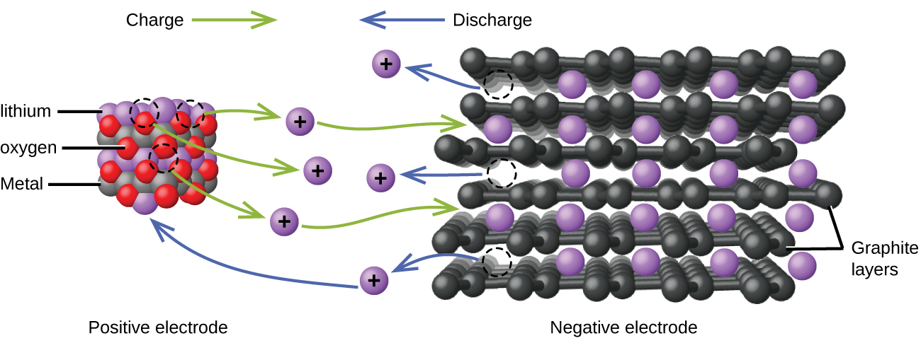
Lithium ion batteries (Figure 3) are among the most popular rechargeable batteries and are used in many portable electronic devices. The reactions are:

Anode: LiCoO2 Lix-1CoO2 + x Li+ + x e
Cathode: x Li+ + x e + x C6 x LiC6
Overall: LiCoO2 + x C6 Lix-1CoO2 + x LiC6

With the coefficients representing moles, x is no more than about 0.5 moles. The battery voltage is about 3.7 V. Lithium batteries are popular because they can provide a large amount current, are lighter than comparable batteries of other types, produce a nearly constant voltage as they discharge, and only slowly lose their charge when stored.

This figure shows a model of the flow of charge in a lithium ion battery. At the left, an approximately cubic structure formed by alternating red, grey, and purple spheres is labeled below as “Positive electrode.” The purple spheres are identified by the label “lithium.” The grey spheres are identified by the label “Metal.” The red spheres are identified by the label “oxygen.” Above this structure is the label “Charge” followed by a right pointing green arrow. At the right is a figure with layers of black interconnected spheres with purple spheres located in gaps between the layers. The black layers are labeled “Graphite layers.” Below the purple and black structure is the label “Negative electrode.” Above is the label “Discharge,” which is preceded by a blue arrow which points left. At the center of the diagram between the two structures are six purple spheres which are each labeled with a plus symbol. Three curved green arrows extend from the red, purple, and grey structure to each of the three closest purple plus labeled spheres. Green curved arrows extend from the right side of the upper and lower of these three purple plus labeled spheres to the black and purple layered structure. Three blue arrows extend from the purple and black layered structure to the remaining three purple plus labeled spheres at the center of the diagram. The base of each arrow has a circle formed by a dashed curved line in the layered structure. The lowest of the three purple plus marked spheres reached by the blue arrows has a second blue arrow extending from its left side which points to a purple sphere in the purple, green, and grey structure.
Figure 3. In a lithium ion battery, charge flows between the electrodes as the lithium ions move between the anode and cathode.

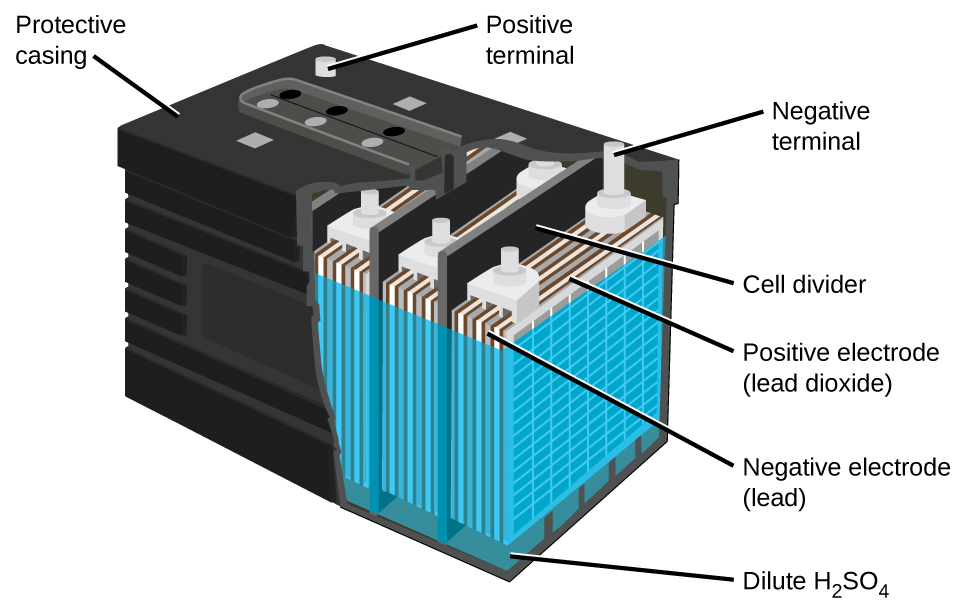
The lead acid battery (Figure 4) is the type of secondary battery used in your automobile. It is inexpensive and capable of producing the high current required by automobile starter motors. The reactions for a lead acid battery are:

Anode: Pb(s) + HSO4(aq) PbSO4(s) + H+(aq) + 2 e
Cathode: PbO2(s) + HSO4(aq) + 3 H+(aq) + 2 e PbSO4(s) + 2 H2O(ℓ)
Overall: Pb(s) + PbO2(s) + 2 H2SO4(aq) 2 PbSO4(s) + 2 H2O(ℓ)

Each cell produces 2 V, so six cells are connected in series to produce a 12 V car battery. Lead acid batteries are heavy and contain a caustic liquid electrolyte, but are often still the battery of choice because of their high current density. Since these batteries contain a significant amount of lead, they must always be disposed of properly.

A diagram of a lead acid battery is shown. A black outer casing, which is labeled “Protective casing” is in the form of a rectangular prism. Grey cylindrical projections extend upward from the upper surface of the battery in the back left and back right corners. At the back right corner, the projection is labeled “Positive terminal.” At the back right corner, the projection is labeled “Negative terminal.” The bottom layer of the battery diagram is a dark green color, which is labeled “Dilute H subscript 2 S O subscript 4.” A blue outer covering extends upward from this region near the top of the battery. Inside, alternating grey and white vertical “sheets” are packed together in repeating units within the battery. The battery has the sides cut away to show three of these repeating units which are separated by black vertical dividers, which are labeled as “cell dividers.” The grey layers in the repeating units are labeled “Negative electrode (lead).” The white layers are labeled “Postive electrode (lead dioxide).”
Figure 4. The lead acid battery in your automobile consists of six cells connected in series to give 12 V. Their low cost and high current output makes these excellent candidates for providing power for automobile starter motors.

Fuel Cells

A fuel cell is a device that converts chemical energy into electrical energy. Fuel cells are similar to batteries but require a continuous source of fuel, often hydrogen. They will continue to produce electricity as long as fuel is available. Hydrogen fuel cells have been used to supply power for satellites, space capsules, automobiles, boats, and submarines (Figure 5).

A diagram is shown of a hydrogen fuel cell. At the center is a narrow vertical rectangle which is shaded tan and labeled “Electrolyte.” To the right is a slightly wider and shorter purple rectangle which is labeled “Cathode.” To the left is a rectangle of the same size which is labeled “Anode.” Grey rectangles that are slightly wider and longer are at the right and left sides, attached to the purple and blue rectangles. On the right side, a white region overlays the grey rectangle. This white region provides a pathway for O subscript 2 to enter at the upper left, move inward and along the interface with the purple region, and exit to the lower right. A similar pathway overlays the grey region on the left, allowing a pathway for the entry of H subscript 2 from the upper right along the interface with the blue rectangle, allowing for the exit of H subscript 2 O out to the lower left of the diagram. Black line segments extend upward from the blue and purple regions. These line segments are connected by a horizontal segment that has a yellow zig zag shape at the center. This shape is labeled “Electric power.” At the left of the diagram, in the upper left white region, 2 H subscript 2 is followed by an arrow that points right and down to H subscript 2. An arrow points right into the blue region to H subscript 2 O. A curved arrow point up to e superscript negative. Another e superscript negative is placed nearby and has an upward pointing arrow extending up to the left of the line segment extending from the purple region. A second arrow points upward along this segment with the label “e superscript negative” to its left. A curved arrow extends down and to the left from the H subscript 2 O into the white region. A second H subscript 2 O is shown below the first in the blue region repeating the arrow patterns established above. At the lower left, an arrow points left, to the exit of the white region. At the tip of this arrow is the label “2 H subscript 2 O.” In the central brown region, O superscript 2 negative is listed twice with arrows pointing left, to the H subscript 2 O formulas in the blue region. At the upper right, O subscript 2 is shown with an arrow pointing left and down to O subscript 2 in the white region. An arrow points left from this point into the purple region. From the tip of the arrow, two arrows point to the two O subscript 2 negative structures in the brown central region. An arrow, labeled “e superscript negative” points downward to the right of the line segment above the purple region. A second arrow extends down into the purple region, pointing to e superscript negative. Three additional e superscript negative symbols appear nearby. An arrow extends from them to the point where the arrows meet in the purple region.
Figure 5. In this hydrogen fuel-cell schematic, oxygen from the air reacts with hydrogen, producing water and electricity.

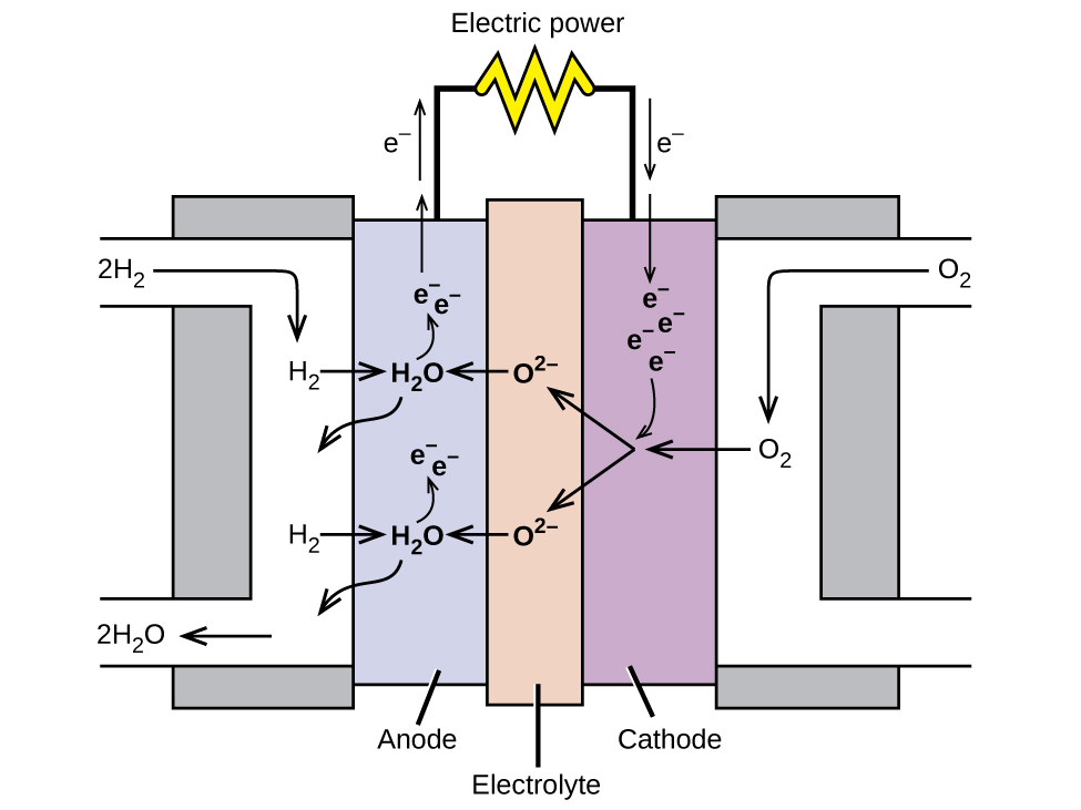
In a hydrogen fuel cell, the reactions are

Anode: 2 H2(g) + 2 O2-(aq) 2 H2O(ℓ) + 4 e
Cathode: O2(g) + 4 e 2 O2-(aq)
Overall: 2 H2(aq) + O2(aq) 2 H2O(ℓ)

The voltage produced about 0.9 V. The efficiency of fuel cells is typically about 40% to 60%, which is higher than the typical internal combustion engine (25% to 35%) and, in the case of the hydrogen fuel cell, produces only water as exhaust. Currently, fuel cells are rather expensive and contain features that cause them to fail after a relatively short time.

Key Concepts and Summary

In this section, we look at a three applications of electrochemical cells. Primary batteries are single-use batteries often used in electronics that do not use large amounts of electricity (i.e. smoke alarms, remote controls, etc). Secondary batteries are rechargeable and are used when continuous electricity is needed (i.e. smartphones, portable computers, cars, etc). Fuel cells are an extremely efficient way to convert chemical energy into electrical energy and are used to supply power for satellites, space capsules, and some automobiles.

Glossary

alkaline battery
a common primary battery that used alkaline electrolytes, such as potassium hydroxide
battery
an electrochemical cell (or series of cells) that produce an electric current
fuel cell
a device that converts chemical energy into electrical energy and requires a continuous source of fuel (often hydrogen)
lead acid battery
a type of rechargeable battery used in your automobile to produce a high current required by automobile starter motors
lithium ion batteries
a popular rechargeable battery that consists of an anode reaction with LiCoO2 and a cathode reaction with Li and C6.
nickel-cadmium (NiCd)
a battery that consists of a nickel-plated cathode, cadmium-plated anode, and a potassium hydroxide electrode
primary battery
single-use batteries that cannot be recharged
secondary battery
batteries that can be recharged

Chemistry End of Section Exercises

  1. List some things that are typically considered when selecting a battery for a new application.
  2. Why do batteries go dead, but fuel cells do not?
  3. Explain why battery-powered electronics can perform poorly in low temperatures.

Answers to Chemistry End of Section Exercises

  1. Considerations include: cost of the materials used in the battery, toxicity of the various components (what constitutes proper disposal), should it be a primary or secondary battery, energy requirements (the “size” of the battery/how long should it last), will a particular battery leak when the new device is used according to directions, and its mass (the total mass of the new device).
  2. Batteries are self-contained and have a limited supply of reagents to expend before going dead. Alternatively, battery reaction byproducts accumulate and interfere with the reaction. Because a fuel cell is constantly resupplied with reactants and products are expelled, it can continue to function as long as reagents are supplied.
  3. Ecell, as described in the Nernst equation, has a term that is directly proportional to temperature. At low temperatures, this term is decreased, resulting in a lower cell voltage provided by the battery to the device—the same effect as a battery running dead.
Comments
Please use this form to report any inconsistencies, errors, or other things you would like to change about this page. We appreciate your comments. 🙂

License

Icon for the Creative Commons Attribution-NonCommercial-ShareAlike 4.0 International License

Chem 103/104 Resource Book Copyright © by Chem 103 Textbook Team and Chem 104 Textbook Team is licensed under a Creative Commons Attribution-NonCommercial-ShareAlike 4.0 International License, except where otherwise noted.