
D11.5 Resonance Structures
Although the molecular orbitals of a polyatomic molecule span the entire molecule, a pair of electrons in a single Lewis structure can only be depicted as shared between two atoms or localized to a single atom. In many situations, this localized bonding picture adequately represents the actual molecule. But in other cases, such as when there are delocalized electron distributions in π bonds, a single Lewis structure is not sufficient for understanding molecular properties and chemical reactivity.
For example, two Lewis structures can be drawn for the nitrite anion, NO2−, both of which satisfy the guidelines for the best Lewis structure for NO2‾:
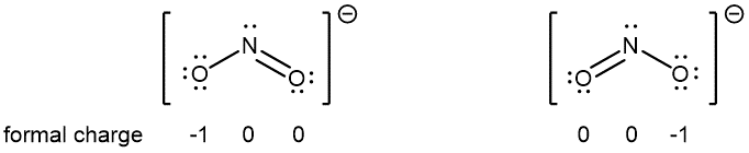
Note that in these two Lewis structures, each of the three atoms is in the same position. The difference is only in the location of electrons. In other words, these two Lewis structures convey the idea that the π bond may be between right O and central N or between central N and left O.
If the NO2‾ molecule is correctly described by only one of the Lewis structures, we would expect one N-O bond to be longer than the other. However, experiments show that both bonds in NO2− are the same length. Moreover, both bonds are longer than a typical N=O double bond and shorter than a typical N-O single bond. Hence, neither Lewis structure alone is a correct depiction of the actual molecule, and the best representation of NO2− is an average of these two Lewis structures.
When the actual distribution of electrons is a weighted average of a set of Lewis structures, those Lewis structures are called resonance structures. The actual electronic structure of the molecule (the weighted average of the resonance forms) is called a resonance hybrid. A double-headed arrow (↔) between Lewis structures indicates that resonance structures are being depicted:
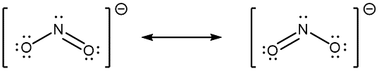
A molecule does not fluctuate between resonance structures; rather, the actual electronic structure is always the weighted average of the resonance structures. In other words, a single Lewis structure is insufficient to correctly represent the molecule (a shortcoming of a simple diagram), and a set of resonance structures (a resonance hybrid) is a better representation.
In the specific case of NO2‾, the two resonance structures drawn above are needed to correctly depict the two electrons that occupy the π molecular orbital that is delocalized over the entire molecule:
Recall that π bonds are formed from unhybridized p atomic orbitals. The two O atoms in NO2‾ have nhyb = 2 and are sp hybridized; the N atom has nhyb = 3 and is sp2 hybridized. Therefore, each of the three atoms has at least one unhybridized 2p atomic orbital that can participate in the π bonding.
The carbonate anion, CO32−, provides another example of the need for a set of resonance structures (the nonzero formal charges are indicated next to respective atoms; it is circled for clarity):
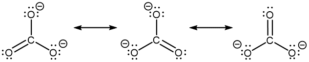
Experiments show that all three C–O bonds are exactly the same. In other words, the two electrons in the π bond are delocalized over the entire molecule, as opposed to being only between one oxygen atom and the carbon atom.
Some guidelines for drawing a set of resonance structures:
- Each resonance structure should have the same number of electrons.
- Formal charge is a useful tool for keeping track of the number of electrons.
- Between resonance structures, atom locations are fixed: only the locations where the electrons are shown changes.
- However, you can draw a set of resonance structures in any perspective. For example, it is perfectly fine to draw the CO32− resonance structures as
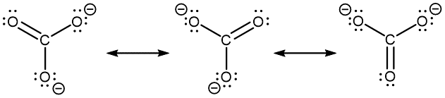
- However, you can draw a set of resonance structures in any perspective. For example, it is perfectly fine to draw the CO32− resonance structures as
- Double-headed arrows between Lewis structures communicate that what is drawn is a set of resonance structures.
In NO2‾, the two major resonance structures contribute equally to the resonance hybrid. This also allows us to approximate the bond order of each nitrogen-oxygen bond in NO2‾ to be 1.5, somewhere between a single and a double bond. Similarly, the three major resonance structures of CO32− contribute equally to the resonance hybrid, and the carbon-oxygen bond order is approximately 1.3.
We said a resonance hybrid is a weighted average because it is possible for some resonance structures to contribute more than others to the resonance hybrid. For example, consider these three resonance structures of cyanate ion (OCN–):
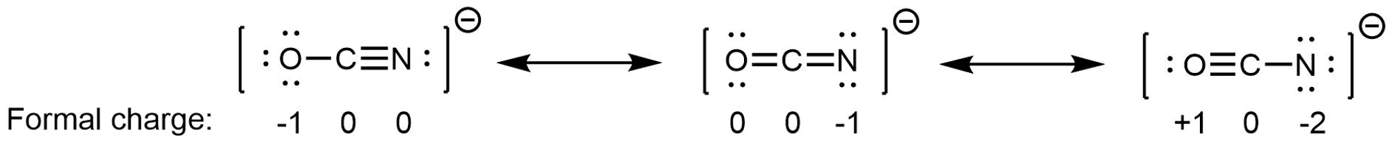
The atoms in each resonance structure have a full octet, but the structures differ in stability because of the way formal charges are arranged. Hence each resonance structure does not contribute equally to the resonance hybrid.
Based on rules for formal charges, the resonance structure on the right contributes the least; that arrangement of electrons is the least stable of the three. The resonance structure on the left contributes more than the middle structure because the left structure has the -1 formal charge on the more electronegative O atom. (For OCN–, quantum mechanics calculations show that the left structure contributes 61% to the resonance hybrid, the middle structure contributes 30%, and the right resonance structure contributes only 4%.)
Again, the actual electronic structure of an OCN– ion is the weighted average of the resonance structures, it is not fluctuating between them. We can gauge the relative contributions of each resonance structure by considering the relative stability of the electron arrangements they represent, but any single resonance structure is insufficient for describing the actual OCN– ion.
Please use this form to report any inconsistencies, errors, or other things you would like to change about this page. We appreciate your comments. 🙂
