D40.3 Standard Half-Cell Potentials

A cell potential results from the difference in the electrical potential between the half-cells. It is not possible to measure directly the potential of a single half-cell; one half-cell has to be connected to another half-cell to measure a voltage.

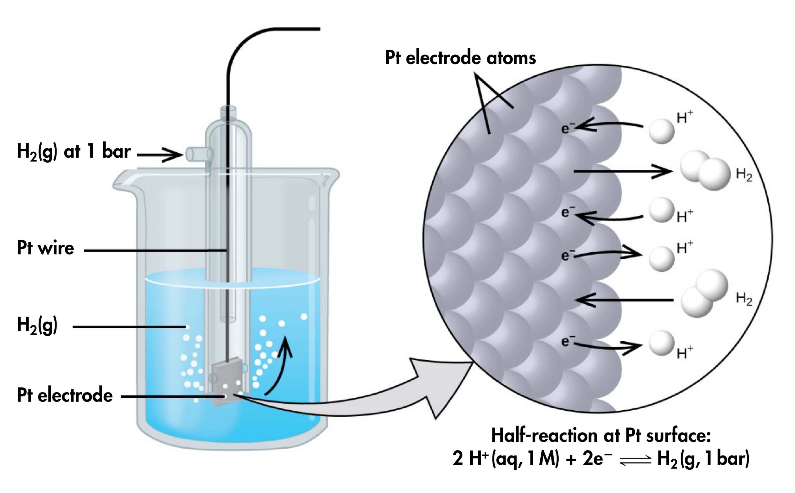
However, it is useful to tabulate potentials for individual half-cells, such that the potential for a voltaic cell constructed from any two half-cells can be calculated from the values in the table. To create such a table, all half-cell potentials need to be measured relative to the same reference half-cell. That half-cell is the standard hydrogen electrode (SHE), which consists of hydrogen gas at 1 bar pressure bubbling through a 1 M H+(aq) solution (platinum is used as the inert electrode):

2 H+(aq, 1 M) + 2 e‾ ⇌ H2(g, 1 bar)          E° = 0 V
The figure shows a beaker just over half full of a blue liquid. A glass tube is partially submerged in the liquid. Bubbles, which are labeled “H subscript 2 ( g )” are rising from the dark grey square, labeled “P t electrode” at the bottom of the tube. A curved arrow points up to the right, indicating the direction of the bubbles. A black wire which is labeled “P t wire” extends from the dark grey square up the interior of the tube through a small port at the top. A second small port extends out the top of the tube to the left. An arrow points to the port opening from the left. The base of this arrow is labeled “H subscript 2 ( g ) at 1 b a r .” A light grey arrow points to a diagram in a circle at the right that illustrates the surface of the P t electrode in a magnified view. P t atoms are illustrated as a uniform cluster of grey spheres which are labeled “P t electrode atoms.” On the grey atom surface, the label “e superscript negative” is shown 4 times in a nearly even vertical distribution to show electrons on the P t surface. A curved arrow extends from a white sphere labeled “H superscript plus” at the right of the P t atoms to the uppermost electron shown. Just below, a straight arrow extends from the P t surface to the right to a pair of linked white spheres which are labeled “H subscript 2.” A curved arrow extends from a second white sphere labeled “H superscript plus” at the right of the P t atoms to the second electron shown. A curved arrow extends from the third electron on the P t surface to the right to a white sphere labeled “H superscript plus.” Just below, an arrow points left from a pair of linked white spheres which are labeled “H subscript 2” to the P t surface. A curved arrow extends from the fourth electron on the P t surface to the right to a white sphere labeled “H superscript plus.” Beneath this atomic view is the label “Half-reaction at P t surface: 2 H superscript plus ( a q, 1 M ) plus 2 e superscript negative right pointing arrow H subscript 2 ( g, 1 b a r ).”
Figure: Standard hydrogen electrode. Hydrogen gas at 1 bar is bubbled through 1 M HCl solution. Platinum, which is inert to the action of the 1 M HCl, is used as the electrode. Electrons on the surface of the electrode combine with H+ in solution to produce hydrogen gas.

If a cell is set up with the SHE on the left and the half-cell whose potential we want to measure on the right, with all concentrations 1 M and all gas partial pressures 1 bar, then the reading on the voltmeter is E°, the standard half-cell potential, for the half-cell on the right. (Unless specified, the temperature is typically assumed to be 25 ºC.)

For example, a voltaic cell consisted of a SHE and a Cu2+ | Cu(s) half-cell can be used to determine the standard half-cell potential for Cu2+ | Cu(s).

This figure contains a diagram of an electrochemical cell. Two beakers are shown. Each is just over half full. The beaker on the left contains a clear, colorless solution and is labeled below as “1 M H superscript plus.” The beaker on the right contains a blue solution and is labeled below as “1 M C u superscript 2 plus.” A glass tube in the shape of an inverted U, a salt bridge, connects the two beakers at the center of the diagram. The tube contents are colorless. The ends of the tube are beneath the surface of the solutions in the beakers and a small grey plug is present at each end of the tube. The beaker on the left has a glass tube partially submersed in the liquid. Bubbles are rising from a grey square, labeled “Standard hydrogen electrode”, at the bottom of the tube. A black wire extends from the grey square up the interior of the tube through a small port at the top to a rectangle with a digital readout of “positive 0.337 V” which is labeled “Voltmeter.” The wire connects to the negative terminal of the voltmeter. A second small port extends out the top of the tube to the left. An arrow points from the left to the port opening. The base of this arrow is labeled “H subscript 2 ( g ) 1 bar.” The beaker on the right has an orange-brown strip that is labeled “C u strip” at the top. A wire extends from the top of this strip to the voltmeter, connecting to the positive terminal. The solution in the right beaker is labeled “1-M H superscript plus.”
Figure: Measuring standard half-cell potential. A voltaic cell involving the standard hydrogen electrode can be used to determine the standard half-cell potential of Cu2+ | Cu(s).

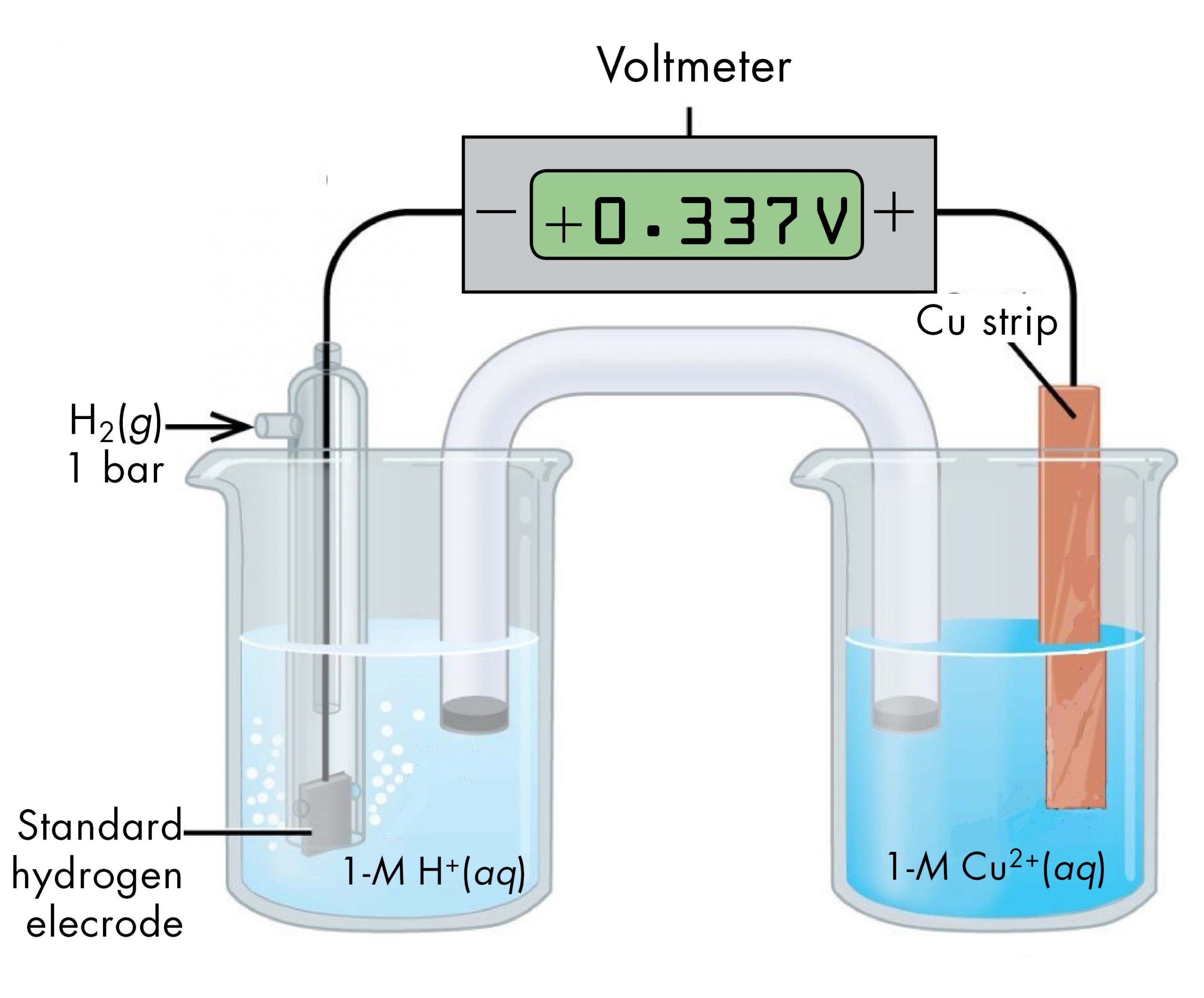
The cell notation for this voltaic cell is:

Pt(s) | H2(g, 1 bar) | H+(aq, 1 M) || Cu2+(aq, 1 M) | Cu(s)

As we noted earlier, the cell potential, E°cell, measured by the voltmeter, is the difference between the potential of the right-hand half-cell and the left-hand half-cell:

E°cell = E°right half-cellE°left half-cell

From the measured E°cell = +0.337 V and the defined potential of zero for the Pt(s) | H2(g, 1 bar) | H+(aq, 1 M) half-cell, we can calculate E° of the Cu2+(aq, 1 M) | Cu(s) half-cell:

+0.337 V = Cu2+|CuH+|H2 = Cu2+|Cu – 0 = Cu2+|Cu

Sometimes, when a cell is set up with the SHE on the left, the reading on the voltmeter is negative. That is, for some half-cells the standard half-cell potential is lower than the potential for the Pt(s) | H2(g, 1 bar) | H+(aq, 1 M) half-cell. Consider the cell shown below, with cell notation:

Pt(s) | H2(g, 1 bar) | H+(aq, 1 M) || Zn2+(aq, 1 M) | Zn(s)
This figure contains a diagram of an electrochemical cell. Two beakers are shown. Each is just over half full. The beaker on the left contains a clear, colorless solution which is labeled “H N O subscript 3 ( a q ).” The beaker on the right contains a clear, colorless solution which is labeled “1 M H superscript plus ( a q ).” A glass tube in the shape of an inverted U salt bridge connects the two beakers at the center of the diagram. The tube contents are colorless. The ends of the tubes are beneath the surface of the solutions in the beakers and a small grey plug is present at each end of the tube. The beaker on the left has a glass tube partially submerged in the liquid. Bubbles are rising from a grey square, labeled “Standard hydrogen electrode” at the bottom of the tube. A black wire extends from the grey square up the interior of the tube through a small port at the top to a rectangle with a digital readout of “negative 0.76 V” which is labeled “Voltmeter.” There is a minus sign where the wire connects to the voltmeter. A second small port extends out the top of the tube to the left. An arrow points to the port opening from the left. The base of this arrow is labeled “H subscript 2 ( g ) 1 bar.” The beaker on the right has a gray strip that is labeled “Z n strip.” A wire extends from the top of this strip to the voltmeter where it connects to the positive terminal. The solution in the beaker on the right has the label “1-M Z n superscript 2 superscript plus ( a q )”
Figure: E°Zn2+|Zn. This voltaic cell can be used to determine the standard half-cell potential of the Zn2+(aq, 1 M) | Zn(s) half-cell. The SHE on the left has a standard half-cell potential of zero.

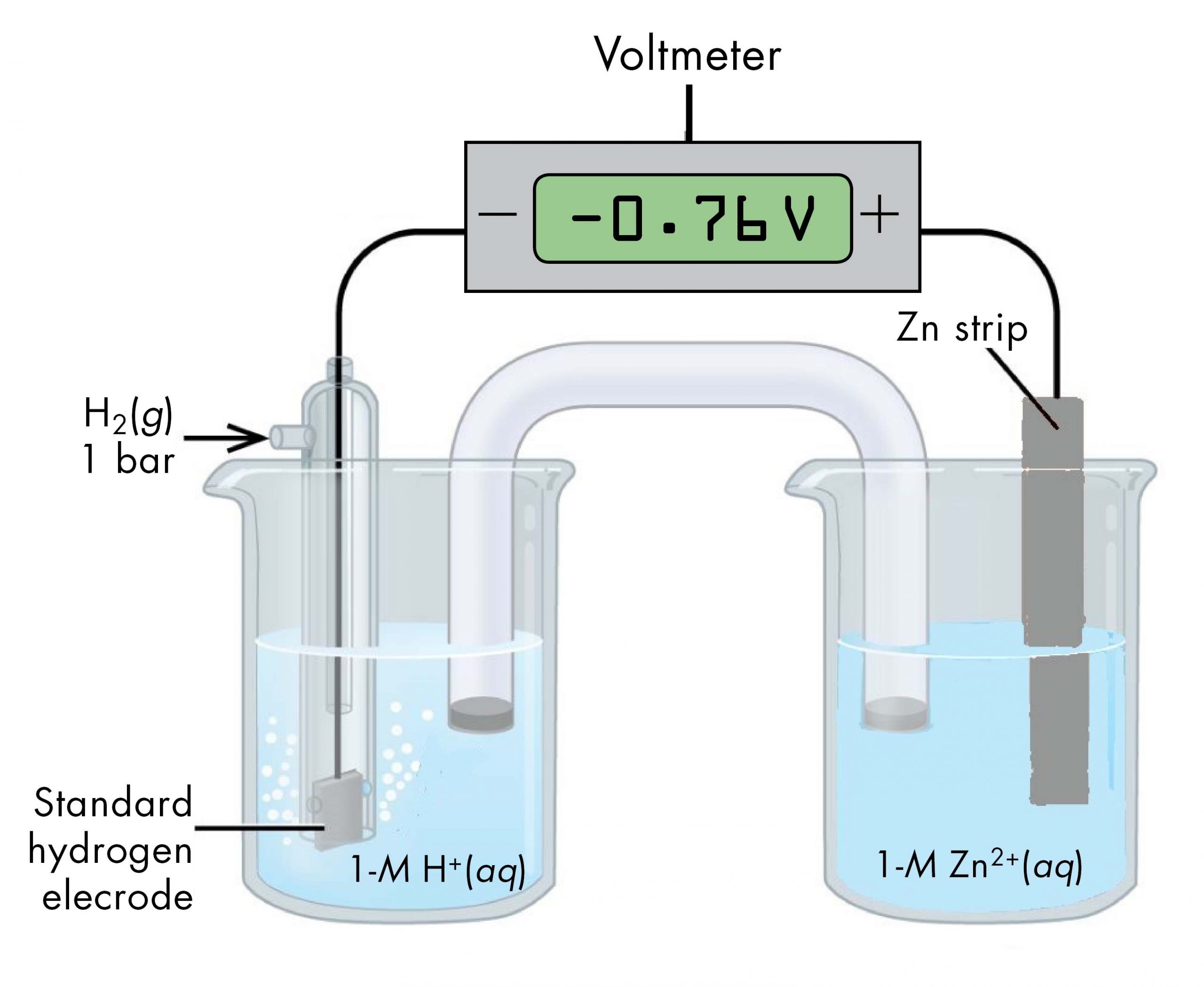
Following the same reasoning as for the Cu2+(aq, 1 M) | Cu(s) half-cell, E° of the Zn2+(aq, 1 M) | Zn(s) half-cell can be calculated.

E°cell = E°right half-cellE°left half-cell
-0.76 V = E°Zn2+|ZnE°H+|H2 = E°Zn2+|Zn – 0 = E°Zn2+|Zn

It may seem strange that the standard half-cell potential is negative. This just reflects the fact that the electrical potential of the Zn2+(aq, 1 M) | Zn(s) half-cell is lower than the electrical potential of the Pt(s) | H2(g, 1 bar) | H+(aq, 1 M) half-cell.

The standard hydrogen electrode is rather dangerous because H2(g) is very flammable. Hence, it is rarely used in the laboratory. Its main significance is that it establishes the “zero” for standard half-cell potentials. Most standard half-cell potentials are measured by setting up a voltaic cell with one half-cell of known standard potential and one half-cell of unknown (to be measured) standard potential.

Comments
Please use this form to report any inconsistencies, errors, or other things you would like to change about this page. We appreciate your comments. 🙂

License

Icon for the Creative Commons Attribution-NonCommercial-ShareAlike 4.0 International License

Chemistry 109 Fall 2021 Copyright © by John Moore; Jia Zhou; and Etienne Garand is licensed under a Creative Commons Attribution-NonCommercial-ShareAlike 4.0 International License, except where otherwise noted.